Bathroom Cabinet
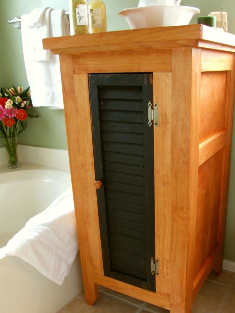
We sized this project to accommodate a reclaimed shutter as the door. You will need to make sure to resize the parts of this project to allow for the size of the door. The finished dimensions are 47-1/2″ tall x 23-1/4″ wide x 24-3/4″ deep.
- 4 – 1x2x8’ Lumber
- 6 – 1x3x8’ Lumber
- 1 – 1x4x8’ Lumber
- 1 – sheet of ¼” plywood
- 1 – sheet of ¾” plywood
- Doorknob hardware
- #18 x 1 ¼” wire brads
- #18 x 5/8” wire brads
- 1 ¼” pocket hole screws
- #17 x 1 ½” wire brads
- European inset hinges
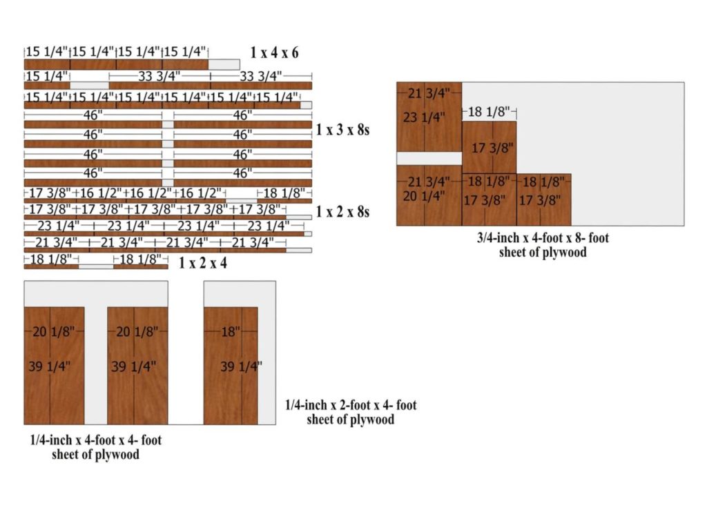
- 4 – 1×4 Lumber @ 15 ¼” long
- 7 – 1×3 Lumber @ 15 ¼” long
- 2 – 1×3 Lumber @ 33 ¾” long
- 8 – 1×3 Lumber @ 46” long
- 3 – 1×2 Lumber @ 16 ½” long
- 6 – 1×2 Lumber @ 17 3/8” long
- 3 – 1×2 Lumber @ 18 1/8” long
- 8 – 1×2 Lumber @ 21 ¾” long
- 2 – 20 1/8” x 39 ¼” – ¼” plywood
- 1 – 18” x 39 ¼” – ¼” plywood
- 3 – 18 1/8” x 17 3/8” – ¾” plywood
- 1 – 21 ¾” x 23 ¼” – ¾” plywood
- 1 – 21 ¾” x 20 ¼” – ¾” plywood
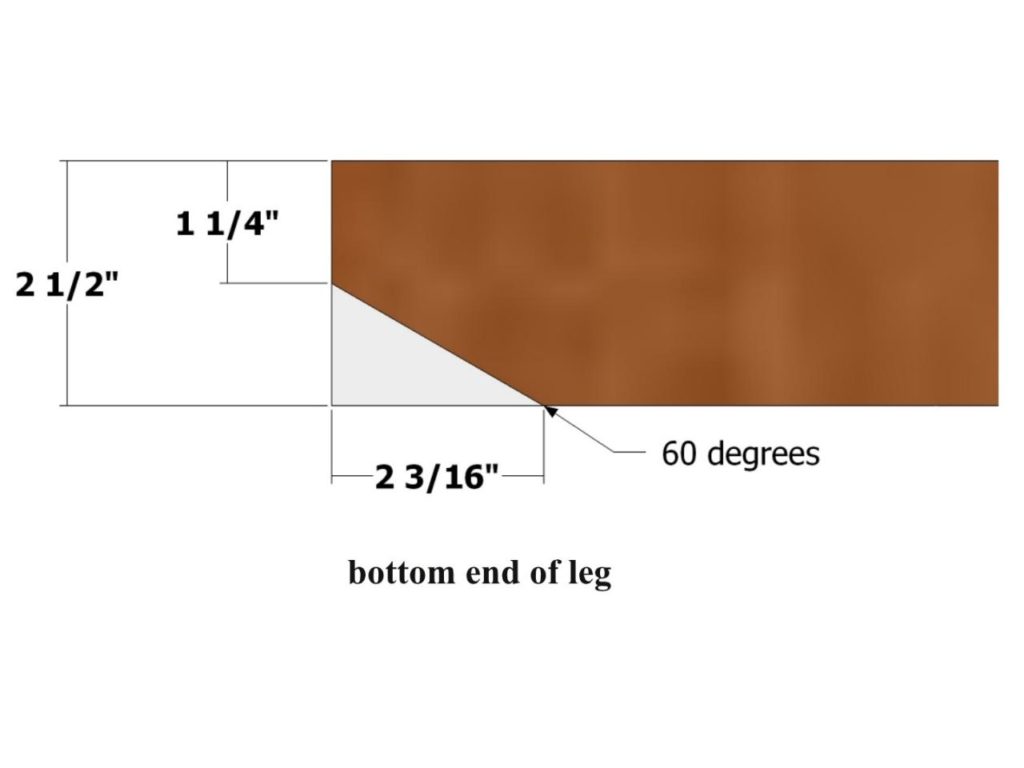
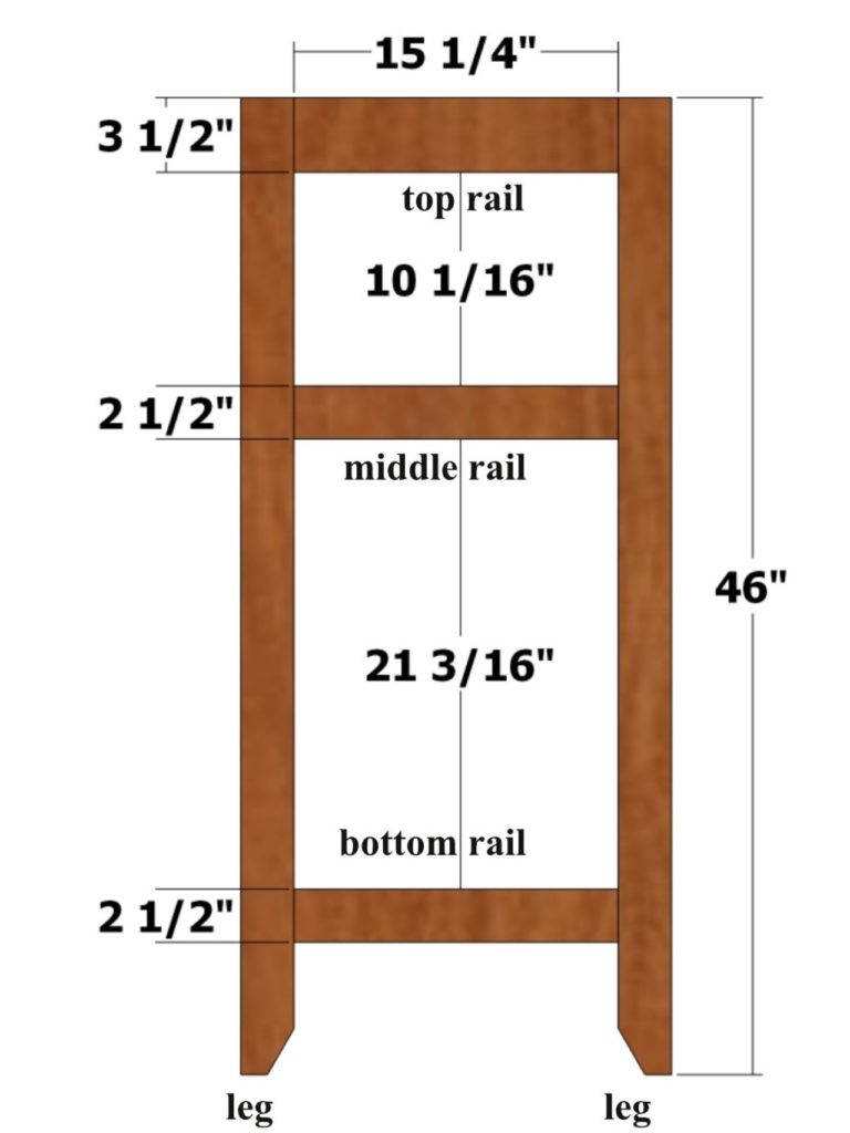
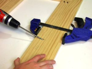
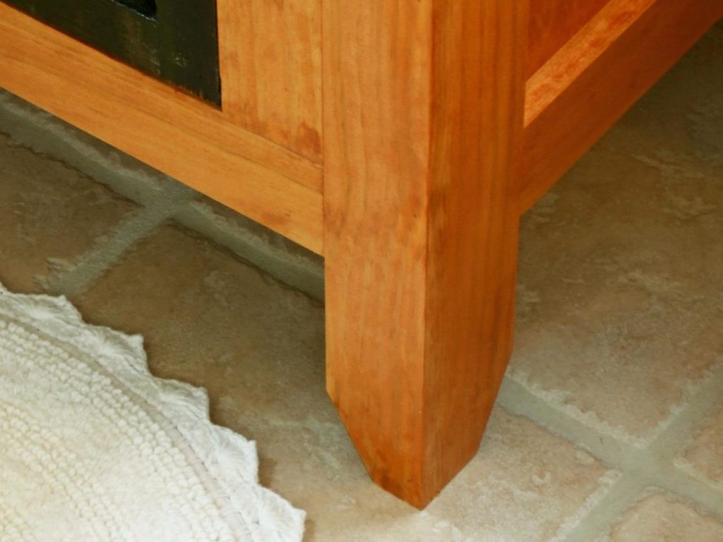
Drill two pocket holes on both ends of the bottom rails, middle rails and top rails. Use Fig. 1 as a guide for cutting to shape the bottom ends of the legs.
Position the bottom rails, middle rails, and top rails as shown in Fig. 2 and attach to the legs using glue and 1-1/4-inch pocket-hole screws. Create three assemblies.
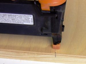
Position the back panel centered and flush with the top of one of the assemblies (be sure to place the panel on the pocket-hole side) and attach using glue and #18 x 5/8-inch wire brads (Fig. 3). Label this the back assembly.
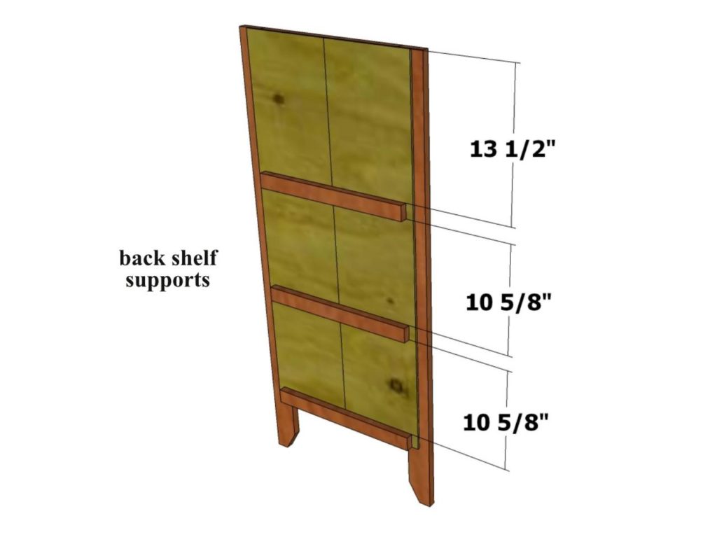
Position the back shelf supports as shown in Fig. 4 and attach using glue and #18 x 1 1/4-inch wire brads. For the back shelf support in the middle, only drive the brads through the last 5/8-inch at the end of the supports.
Position a side panel flush with the top and one end of one assembly (be sure to place the panel on the pocket hole side) and attach using glue and 5/8-inch brads. Attach the remaining side panel to the remaining assembly, making sure it is a mirror image of the previous assembly with the side panel.
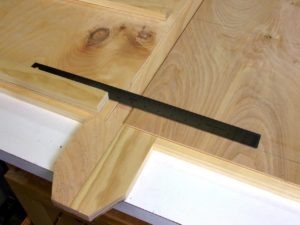
Position the side panel assemblies flush with the back panel assembly as shown in Fig. 5 and scribe the position of the shelf supports onto the side panel assemblies.
Position the side shelf supports spaced apart the same distance as the back shelf supports and attach using glue and 1-1/4-inch wire brads. For the side shelf support in the middle, only drive the brads through the last 5/8-inch at the end of the supports
Drill two pocket holes on each end of the front stiles, and one pocket hole centered and horizontal along the length of the stiles. Position the front stiles flush with the ends of the remaining bottom rail and top rail with the horizontal pocket holes pointing out and attach using glue and 1-1/4-inch pocket-hole screws. Position this assembly flush with the top end of the two remaining legs (make sure the angle cut on the bottom of the legs are facing inward) and attach to the legs using glue and pocket hole screws. Be sure to also drive screws through the horizontal pocket holes on the stiles as shown above.
Position the back assembly flush with the top and back edge of the side assemblies and attach using glue and #17 x 1-1/2-inch wire brads.
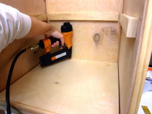
Position the shelf nosing flush with the edge and 18-1/8-inch wide end of the shelves and attach using glue and 1-1/2-inch brads. Build three shelf assemblies.Position the shelves on the shelf supports, beginning with the bottom shelf, with the shelf nosing flush against the front edge of the shelf supports, and attach to the supports (sides and back) using glue and 1-1/2-inch brads as shown in Fig. 7.
Position the front assembly flush with the top and front edge of the side assemblies and attach using glue and #17 x 1-1/2-inch wire brads as shown in above image. Check the assembly for square by measuring it diagonally and clamp in place if needed to attain square until the glue sets.
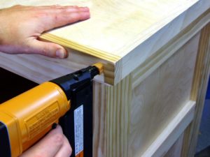
Position the sub top on the top end of the assembly, flush with all edges, and attach using glue and 1-1/2-inch brads. Position a sub top trim part on the front of the assembly, flush with the top edge and sides of the sub top and attach using glue and 1-1/2-inch brads. Position a second sub top trim part on the back of the assembly, flush with the top edge and sides of the sub top and attach using glue and 1-1/2-inch brads. Position the two remaining sub top trim parts flush with the top edge of the sub top and the ends of the first two sub top trim parts, and attach using glue and 1-1/2-inch brads as shown in Fig. 9.
Position the top on the sub top, flush with all edges, and attach using glue and 1-1/2-inch brads. Position a top trim part on the front of the assembly, flush with the top edge and sides of the top and attach using glue and 1-1/2-inch brads. Position a second top trim part on the back of the assembly, flush with the top edge and sides of the top and attach using glue and 1-1/2-inch brads. Position the two remaining top trim parts flush with the top edge of the top and the ends of the first two top trim parts, and attach using glue and 1-1/2-inch brads as shown in Fig. 10.
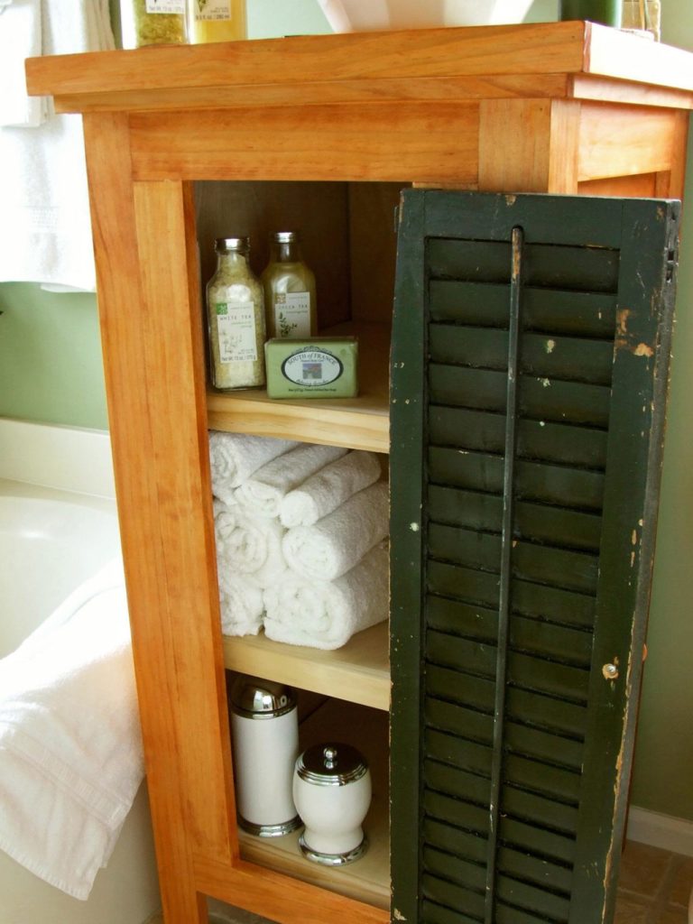
Attach two hinges, spaced equidistantly apart, on the edge of the shutter. Position the shutter centered from in the opening from top to bottom, with a spacer (a paint stirrer works nicely) between the shutter and the front of the assembly. Attach the hinges to the front stile.
Attach a door pull at the desired position on the shutter.
As an option, you can attach a magnetic catch to the shutter and inside of the bath pantry assembly or a latch on the outside of the shutter and bath pantry assembly to keep the door closed.
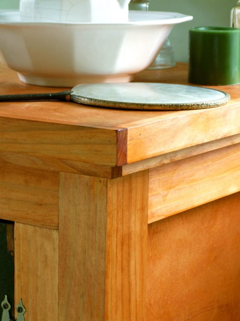
Fill nail holes and apply paint or stain and polyurethane as desired on the project. Depending on the condition of the reclaimed shutter, you may want to apply a coat of polyurethane to seal the shutter.
This original plan can be found at http://www.diynetwork.com/how-to/skills-and-know-how/carpentry-and-woodworking/how-to-build-an-armoire-storage-cabinet

