Bar Cart


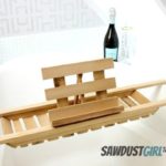
If your usual method of serving beverages at a barbecue involves a Styrofoam cooler and a bag of ice, it’s time to think about an upgrade. This mobile cart is tough enough to withstand sun, rain, and spills of your libation of choice. Two-wheeled construction lets you navigate stone patios or lumpy lawns with ease, and the top tray is removable for serving drinks or munchies. Best of all, the entire thing can be easily taken apart and stored flat—or, better yet, stashed in your trunk for tailgate parties this fall. What better project to celebrate the beginning of grilling season? This Old House senior technical editor Mark Powers shows how to put it together using cedar and outdoor-grade materials.

Step 1: Cut the Pieces

Use a miter saw and a stop block to make cuts of the same length quickly; refer to the illustration for dimensions. For the top tray, cut two 1×4 short sides and two 1×3 long sides. For the bottom tray, cut short and long sides from 1x3s. Cut 19 1×3 bottom boards (nine for the top tray, 10 for the bottom one). Rip a 1×2 in half and cut four ledges to support the bottom boards.

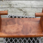
Cut 2x deck pickets to make crosspieces to support the removable top tray. Cut the cart’s handle from a 1-inch hardwood dowel. Cut off the corners of the top tray’s 1×4 short sides so that each edge is 2½ inches tall and even with the height of the long sides. Use a wood file to round over the cuts, then smooth the cut pieces with sandpaper and a block.

Step 2: Cut out the top tray’s handles

Use a paint can to trace a centered arc to make a handle on both 1×4 (short) tray sides. Make sure the cuts are at least ½ inch below the top edge and 1¾ inches above the bottom edge of the 1×4. Use a jigsaw to cut out the handles. Use a file to smooth the cut surfaces.

Step 3: Attach ledges to Long sides

Lay a long side on the flat, and use a 1×3 turned on edge to mark off space at the ends, where the short sides will be attached. Apply wood glue along one edge of the long side between the marks. Press a ledge into the glue, flush with the edge of the side piece. Use the nail gun to drive 1 3⁄8-inch nails a few inches apart through the ledge and into the long side. Repeat for the three remaining long sides.

Step 4: Make the tray frames

Apply glue to the cut edge of a short side and the end of a long side. Butt the pieces together to form a corner. Use the nail gun to drive a nail through the top and bottom of the long side and into the edge of the short side. Repeat for all joints for tray frames.

Step 5: Attach the boards

Apply glue to the ledges of the top tray. Lay nine 1×3 boards across the ledges, using a couple of screws as spacers between them to facilitate drainage. Use the nail gun to secure the ends of the boards to the ledges. Repeat for the bottom tray, using 10 boards.

Step 6: Cut and Mark the legs

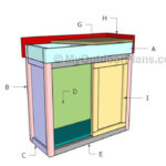
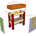
Refer to the illustration for all dimensions. Use a miter saw to make parallel 45-degree cuts on four 1x2s to cut them to size. Cut ¼ inch off the long points at each end. Lay the A legs on the flat and side by side, with the cut-off long points flush at one end, as shown (the short points meet at the other end). Mark each leg’s surface as an “outside face.” Measure and mark hole and notch locations on both legs. Repeat for the B legs, but mark each leg’s surface as an “inside face.”

Turn all the legs on edge. Mark each one at the midpoint of the edge, between the marks, to designate the depth of the notch cuts.

Tip: When marking multiple pieces to be drilled or cut in the same spots, measure off the first one and use a combination square to transfer the marks to other pieces at the same time.

Step 7: Make the notches

Using a miter saw, make several kerf cuts between the notch marks on the outside faces of the A legs and the inside faces of the B legs. Stop at the midpoint you marked in step 7. Use a chisel to remove the wood.

Step 8: Drill holes and Recesses

Using a drill/driver, with bits sized to the holes shown on the illustration, drill holes through the legs, except for holes through the notches. On the outside faces of the A legs, drill countersinks for the cart handle’s screws. Flip the A legs over; on the inside faces, center a 1-inch paddle bit over the countersinks and make ¼-inch recesses for the handle. Smooth cuts with sandpaper.

Step 9: Assemble the sides

Fit together the notches on the A and B legs for one side of the cart. Drill a centered ¼-inch hole through both legs at the notched intersection. Slip the post end of a 5⁄8-inch screw post through the notch hole in the B leg. Lay the legs on a work surface, A leg facing up, and slip the screw end of the screw post into the notch hole in the A leg. Begin screwing it into the post by hand, then tighten with a screwdriver. Repeat for the second side of the cart.

Step 10: Drill pilot holes for the bottom tray

Refer to the illustration for hole locations. Measure and mark spots for pilot holes for the bottom tray; make sure they’re ½ inch above the tray’s bottom. Use a 3⁄8-inch bit to drill four holes through the tray’s long sides and ledges.

Tip: When drilling large pilot holes, begin with a smaller bit size to create an accurate path through the material, then step up to the larger one.

Step 11: Add insert nuts to the bottom tray

Using a flathead screwdriver, screw threaded brass insert nuts into the holes you drilled in step 11; these will accommodate the hex-head connector bolts you’ll use to attach the sides of the cart in step 14.

Step 12: Add insert nuts to the cross pieces

At the ends of each crosspiece, find the center by drawing two lines from corner to corner. Repeat steps 11 and 12 to drill holes and add insert nuts at these spots.

Step 13: Assemble the Cart Bottom

Stand the bottom tray on a long side and the crosspieces on their ends. Lay one set of the cart’s legs over these pieces, handle recess facing down. Line up the pilot holes with the insert nuts in the tray and crosspieces. Using a hex key, twist hex-head connector bolts through the holes and into the nuts. Fit one end of the handle into the recess, and use a 1½-inch stainless-steel screw to secure it to the leg through the countersink.

Step 14: Attach the second side

Flip the cart over so that the attached side sits on the work surface. Thread the axle through the 5⁄16-inch axle hole, which is on the A leg, beneath the bottom tray of the attached side. Fit the axle hole of the cart’s second side over the axle. Line up the pilot holes, and attach the second side of the cart as described in step 14.

Step 15: Attach Wheels to the Axle

Slip the wheels onto the axle. Insert cotter pins through the holes at the axle’s ends, and bend their legs around the axle to keep the wheels in place. Cover the ends of the axle with the axle caps (included).

Tip: If you can’t bend the legs of the cotter pins by hand, use a pair of needle-nose pliers to get the job done.

Step 16: Build the bottle rack

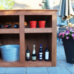
Refer to the illustration for dimensions. Cut two 1×4 long sides, two 1×3 short sides, and three 1×3 bottle spacers. Follow the process in step 4 to glue, butt, and nail the joints together. Start by attaching the edge of a long side to the end of a short side so that they’re flush at their top edges. Next, attach the edges of the spacers along the inside face of the long side, flush with its bottom edge and spaced at proper intervals (use bottles to size them). Attach the second long side to the end of the first short side and the edges of the spacers; it should be flush with the top of the short side and the bottoms of the spacers. Finish by attaching the edges of both long sides to the ends of the second short side, flush at their tops. Fit the rack onto either tray to hold bottles in place.

Tip: If you leave the cart unfinished, the cedar will weather to an attractive silvery gray—just like a beach house. If you’d rather preserve the color of the wood or bring out its red undertones, apply a clear toner, such as Penofin, annually.

The original plan is from https://www.thisoldhouse.com

[email_link]

Barbeque Cart

This easy-to-build Barbecue Cart will solve both of those problems for you.  First, it comes complete with two spacious drawers, a condiment organizer, a utensil holder, a slide-out cutting board/shelf and plenty of space for all the cooking stuff you’ll be needing.  The laminate-covered top offers plenty of space for food preparation and staging . . . it’s conveniently portable . . . plus . . . it’s attractive enough to fit in, no matter where you may choose to store it between cook-outs.

We made our example from red oak with a white laminate-covered top and lower shelf.  If you’re planning to leave the table outside, be sure to choose a weatherproof wood like red cedar, redwood or cypress for the basic construction and use waterproof glue and brass screws to put everything together.

List of Materials:

Facing Assembly – Figure 1
A – Stiles(2) 3/4″ x 1 1/2″ x 8″
B – Stile-Middle(1) 3/4″ x 1 1/2″ x 4 1/4″
C – Top Rail(1) 3/4″ x 2 1/4″ x 17″
D – Bottom Rail(1) 3/4″ x 1 1/2″ x 17″

Base Assembly – Figure 2
E – Back(1) 3/4″ x 8″ x 20″
F – Sides(2) 3/4″ x 8″ x 14 1/2″
G – Legs(4) 2″ x 2″ x 38″

Web Frame Assembly – Figures 3 & 4
H – Stiles(2) 3/4″ x 2 1/2″ x 17″
I – Rails(2) 3/4″ x 2 1/2″ x 15 3/4″
J – Stile-Middle(1) 3/4″ x 2 1/2″ x 12 3/4″
K – Drawer Runners(2) 1/4″ x 1″ x 16″
L – Cleats(2) 3/4″ x 2 1/2″ x 16 7/8″

Shelf Support Assembly – Figures 6 & 7
M – Sides(2) 3/4″ x 1 5/8″ x 22 1/4″
N – Back Brace(1) 3/4″ x 1 5/8″ x 12 3/4″
O – Front Brace(1) 3/4″ x 3/4″ x 12 3/4″
P – Guides(2) 3/4″ x 1 1/4″ x 10 3/4″
Q – Side-Out Shelf(1) 11/16″ x 10 3/8″ x 11 1/16″
R – Bottom-Hardboard(1) 1/8″ x 14 1/2″ x 11

Bottom Shelf Assembly – Figures 8 & 9
S – Front/Back Rail(2) 3/4″ x 1 1/2″ x 20
T – Side Rail(2) 3/4″ x 1 1/2″ x 18 1/2″
U – Top-Laminate(1) 3/4″ x 17″ x 18 1/2″

Drawer Assembly – Figure 5
V – Sides(4) 5/8″ x 4 1/16″ x 16″
W – Front/Back(4) 5/8″ x 4 1/16″ x 6 7/8″
X – Bottoms(2) 1/4″ x 6 3/4″ x 15 1/8″
Y – False Fronts(2) 3/8″ x 5″ x 8 1/2″

Top Assembly
Z – Top-Laminate(1) – 3/4″ x 17″ x 18 1/2″
M – Side Rail(2) – 3/4″ x 1 1/2″ x 20 1/4″
BB – Front/Back Rail(2) – 3/4″ x 1 1/2″ x 25 3/4″

Accessory Add-ons
CC – Utensil Holder(1) 3/4″ x 2″ x 17 5/8″
DD – Condiment Hold(1) 3/4″ x 4″ x 18″

Hardware
20 – 1 1/4″ x #8 Wood Screws
14 – 1 ¼” x #6 Wood Screws
4 – Wooden Screw Plugs – Optional
62 – 1” x 3/8” Dowel Pins
1 – 1” x ¼” Dowel Pin
2 – Drawer Pulls
1 – Sliding Shelf Pull
4 – Casters

Figure 1

Step 1:

First, cut all work pieces to size, following the dimensions outlined in the List of Materials

NOTE:  Be sure to allow all glued-up sub-assemblies to dry completely for 24 hours before putting them together with other sub-assemblies.

Step 2:

Using your drill press, drill (16) 3/8-inch diameter by 9/16-inch deep dowel holes in pieces B, C and D, and glue the facing assembly together, using 3/8-inch diameter by 1-inch long dowel pins as shown in Figure 1.

Step 3:

Use your dado set-up or band-saw to cut a 10-7/16-inch wide by 1-9/16-inch deep notch in the left side of the base assembly (F) to accommodate the pull-out shelf/cutting board, which will be installed later. See Figure 2.

Figure 2

Step 4:

Drill (50) 3/8-inch diameter by 9/16-inch deep dowel holes in pieces A, E, F and G as shown in Figure 2.  Assemble all pieces together (including the facing sub-assembly you made in step #2, above) using 3/8-inch diameter by 1-inch long dowel pins.

Step 5:

Mount cleats (L) to the insides of the four legs (G) as shown in Figure 4, using 3/8-inch diameter x 1-inch long dowel pins.  Position them 7-1/4” down from the tops of the legs (G) or sides (F).

Step 6: 

Cut 1/4-inch by 3/8-inch deep tongue & groove joints in the web frame stiles and rails (pieces H, I and J), as shown in Figure 3.

Figure 3

Step 7:

Glue-up the web frame assembly as shown in Figure 3

Step 8:

Mount the web frame assembly to the top surfaces of the cleats you glued into position in step#5, above, using four 1 ¼” x #8 wood screws. See Figures 3 & 4.

Figure 4

Step 9: 

Cut the dado and rabbet joints in the drawer fronts and backs (parts W) and the drawer sides (parts V), as shown in Figure 5.

Step 10: 

Cut the 1-inch wide by 1/4-inch deep notches in the drawer fronts/backs (parts W) (see Figure 5).  These notches will slide on the drawer runners (parts K, Figure 3) when assembled.

Step 11: 

Using glue, assemble the drawer sides (V) front/back (W) and bottom (X), as shown in Figure 5.

Figure 5

Step 12: 

Using the drawer assemblies you made in step 11, above as guides, glue the drawer runners (K) to the web frame assembly as shown in Figure 3.  Be sure the drawers slide smoothly in and out before leaving the runners to dry.

Step 13:

Using a router or belt sander, round-over the edges of the false drawer fronts (Y).

Step 14:

Glue the false drawer fronts (Y) to the fronts of the drawer assemblies (See Figure 5).

Step 15: 

Construct the shelf support assembly (M, N, O, P, R in Figure 6) using 1-1/4″ x #6 wood screws.

TIP:  Drill pilot holes for screws first to ease the assembly process. 

Figure 6

Step 16: 

Mount the completed shelf support assembly (Figure 6) to the base assembly (Figure 2), using 1-1/4-inch x #8 wood screws. See Figures 6 & 7.

Step 17: 

Drill a 1/4-inch diameter by 1/2-inch deep hole, in a centered position, approximately 1/2-inch in from the back edge of the slide-out cutting board/shelf (part Q).  Be sure this hole is in the TOP surface of the board.  This protruding dowel will serve as a stop to keep shelf from pulling out completely.  We’ll glue this stop into position later.

Figure 7

Step 18: 

Cut the miters for the bottom shelf front, back and side rails (parts S & T).  See Figure 8.

Step 19: 

Assemble the bottom shelf with 3/8-inch diameter x 1-inch long dowel pins and glue.  NOTE: Be sure to apply a liberal coat of glue around all edges of the top (U) to prevent any moisture or spills from seeping into the laminate substrate. If you’re planning to leave your Cart outdoors, use waterproof glue. See Figure 8.

Figure 8

Step 20: 

Attach the bottom shelf assembly you made in step 19 to the four legs (G) using 1-1/4-inch x #8 wood screws. We suggest that the shelf be positioned about 10-inch or so up from the bottoms of the legs.  It’s your choice. See Figure 9.

Figure 9

Step 21: 

Cut the miters for the front, back and side rails (AA & BB) of the Cart to assembly (See Figure 10). Next, cut out the utensil holder (CC) and condiment holder (DD) pieces. See Figure 10.

Step 22: 

Using glue and 3/8-inch diameter x 1-inch dowels, put the top assembly together (Z, AA, BB). NOTE:  Be sure to apply a liberal coat of glue around all edges of the top (Z) to prevent any moisture or spills from seeping into the laminate substrate. If you’re planning to leave your Cart outdoors, use waterproof glue. See Figure 10.

Figure 10

Step 23: 

Mount the top assembly to the base assembly, using 1-1/4-inch x #8 wood screws. See Figure 11.

Step 24: 

Mount the utensil holder (CC) to the side of the top assembly using two 1-1/4-inch x #8 wood screws. See Figure 10.

Step 25: 

Round the edges of the condiment holder using a belt sander or router and mount it to the laminate top with four 1-1/4-inch x #6 wood screws. See Figure 10.  If you prefer, counter-bore the screw holes and fill them with wooden plugs.

Step 26: 

Finish sand the entire Cart. Be careful not to scuff your laminate surfaces in the process.

Step 27: 

Apply a stain, oil or other finish of your choice.

Step 28: 

Install the slide-out cutting board/shelf (Q) and glue the 1/4-inch dowel pin into position as a stop.

Step 29: 

Mount the pulls of your choice on the drawers and slide-out shelf.

Step 30: 

Mount the casters

Figure 11


The original plan can be found at http://www.shopsmithhandson.com

<a href=”http://w00dworking.com/wp-content/uploads/2018/01/BBQ-cart.pdf” target=”_blank” rel=”noopener”><img class=”alignnone wp-image-2426 size-full” src=”http://w00dworking.com/wp-content/uploads/2018/01/PDF-icon-small-231×300-e1515477493230.png” alt=”” width=”50″ height=”65″ hspace=”20px” /></a>[email_link]

Barbeque Grill Cart

We recently bought a new gas grill to replace our old cheapie one that rusted out.  It’s a small model that requires a tabletop or a stand. Unfortunately the Weber barbecue grill cart sold separately for this grill is $100. I knew I could make something nicer for half that price.

This barbecue grill cart is beg enough to hold two propane tanks on the lower shelf. I like to have two tanks in case one runs out in the middle of cooking a meal. I’ve included an elevated platform for utensils and plates and the whole unit is mobile, using the wheels from the old grill.

Materials:

8 – 1x4x8 Cedar Boards

  • 15 pieces @ 18″ long
  • 11 pieces @ 15″ long
  • 2 pieces @ 48 1/2″ long
  • 2 pieces @ 36 1/4″ long
  • 4 pieces @ 13 1/2″ long
  • 2 pieces @ 1 1/2″ x 13 1/2″ long
  • 2 pieces @ 1 1/2″ x 12 3/4″ long

2 – 2x4x8 Cedar Boards

  • 2 pieces @ 34 3/4″ long
  • 2 pieces @ 27″ long

1 – 36″ length of 1 1/2″ dowel
2 – Wheels or castors from a old BBQ cart

Directions:

After cutting most of the pieces to length, I drilled 1 1/2″ holes in one end of each of the upper table frame. These will hold the dowel handle. I clamped the two boards together and cut both holes at once to ensure they would line up properly.

I cut a curve on the end of each of these using my bandsaw. I assembled the top frame and the lower frame into simple boxes using pocket screws.

I curved the ends of the two feet. These, and the rear uprights are made from 2x4s. They get glued and screwed into the table frames. I used the wheels from the old cart and attached them using a threaded rod.


I glued the dowel handle in place and attached a frame to the upright for the utensil platform.

To protect everything, I covered all the surfaces with a transparent redwood deck stain and sealer, then screwed all the plans into place on the frames.

The original plan is found at Woodworking for Mere Mortals at https://woodworking.formeremortals.net

[email_link]

Bar – Corner

Owning your own in-house bar makes a statement about you. The bar shown here is sleekly styled and smartly laid out for the efficient barkeeper. A small refrigerator gives you access to cold drinks and ice while convenient cabinets create excellent storage spots for party favors. While this is a “dry bar” (no plumbing), the design could be modified in any number of ways to add running water if you wish. All you need to get the party started is a GFCI electrical outlet and the proper floor space.

This compact corner bar design features glossy black MDF aprons with decorative cherry appliqués forming a horizontal grid pattern on the aprons. A cherry plywood bar top sits atop a 2 × 6 L-shaped knee-wall, harboring some practical amenities on the bartender side. A flip-up lift gate in the bar top on one end provides pass-through access and can even function as a wait station if you want to get really fancy in your hosting. The key components— base cabinets, a laminate counter top, the fridge, and the wood for a sleek Asian inspired style trim-out—set the stage for your next gathering. Let’s party!

Materials:

Directions:

Step 1: Cut the 2 x 6 Sill Plates to Length (68″)

Anchor the sill plates for the knee-walls to the floor so they form a right angle at the corner where they meet. Use 16d common nails or screws and panel adhesive for a wood floor; use a powder-actuated nailer on a concrete floor.

Step 2: Attach the End Stud Against the Back Wall

Use panel adhesive and deck screws to attach the end knee-wall stud to the back wall, attaching at a stud location. If there’s no stud, open the wall and insert a horizontal nailer between the nearest studs.

Step 3: Make the Stud Wall Corner

Use 16d common nails to toe-nail the corner studs to the sill plates. Use a level to make sure the studs are vertical.

Step 4: Cut Cap Plates the Same Size as the Sill Plates

Complete the framing for the L-shaped knee-wall section. For extra strength, drive a few 3″ deck screws through the studs where they meet at the corner.

Step 5: Make the Aprons and Trim

Rip two sheets of 1/2″ MDF to 40 1/2″ wide and trim them to length to make the bar front panels. Sand edges to remove any saw marks. For the smoothest possible finish, spray the front apron panels with an HVLP sprayer. Apply the paint or lacquer over primer, in thin coats.

Step 6: Prepare Hardwood Stock

Prepare at least 80 lineal feet of 3/4 × 11/2″ hardwood stock to trim out the aprons and edges of the bar-top.

Step 7: Apply a Clear Protective Wood Finish

For efficiency, apply a protective finish to the cherry apron trim stock. Dab some finish on the cut ends after you cut each trim piece to length.

Step 8: Apply Panel Adhesive to the Knee-wall Studs

Apply panel adhesive to the knee-wall studs to strengthen the bond with the black aprons. Slip a 1/4-thick spacer beneath each apron to create a gap between the panel and the floor.

Step 9: Attach the Aprons

Attach the aprons with a pneumatic nailer and 2 1/2″ Finish Nails Nail the apron panels to the wall studs at 8″ to 12″ intervals.

Step 10: Cut 16″ Wide Strips of 1/2″-Thick Cement Boards

Attach cement board strips to the edges of the knee-wall framing members as a backer for the backsplash area.

Step 11: Install the Wall Tile

Install the inside wall covering before you cap the wall. We used inexpensive 4 x 4″ ceramic wall tile set into a layer of thin-set adhesive that’s troweled onto the cement board.

Step 12: Bond the Particleboard Sub-base

Bond the particleboard sub-base directly to the top plates of the knee-walls, taking care to achieve even overhangs of 6″ in front and 4″ on the bartender side of the walls.

Step 13: Secure the Sub-base to the Walls

Drive plenty of 2″ deck screws to secure the sub-base to the walls. The screw heads must be sunk beneath the wood surface.

Step 14: Use a Circular Saw to Cut the Bartop

Make 45-degree miter cuts in the bartop top layer using a circular saw and cutting guide.

Step 15: Laminate With Panel Adhesives

Laminate the top layer of cherry plywood to the sub-base with panel adhesives and 1 1/4″ screws driven up through the sub-base.

Step 16: Cut Parts to Length + Attach them to the Edges of the Bar top

Cut a round-over profile in one edge of the cherry edging stock and then cut the parts to length and attach them to the edges of the bartop with nails and glue.

Step 17: Square-Cut a piece of 1 × 2 Edging

Square-cut a piece of 1 × 2 edging to fit exactly between the ends of the round-over edging, and nail and glue it into place.

Step 18: Nail the End Panel to the Wall

Nail the cherry end panel to the wall end to conceal the stud wall and the edges of the wall coverings and trim.

Step 19: Attach a 1 x 2 Stop Block to the Wall

Attach a 1 × 2 stop block for the lift gate to the wall directly above the wall-mounted end panel.

Step 20: Attach the Piano Hinge

Attach the piano hinge to the lift gate section of the countertop first, then attach the other leaf to the countertop.

Step 21: Attach the Lift Gate

Attach the lift gate to the countertop and test to make sure it operates smoothly and correctly.

Step 22: Create a Ladder Grid Pattern

Add the decorative cherry strips in a ladder grid pattern, using an air nailer. Start with the vertical strips, then cut the horizontals to fit.

Step 23: Attach a Countertop to the Base Cabinets

Attach a countertop to the base cabinets to create an easy-to-clean work surface for the bartender.

Step 24: Add a Refrigerator or Appliance of Your Choice (OPTIONAL)

Slide in a refrigerator, or any appliance you choose.
The original plan can be found at http://www.freewoodworkingplan.com

[email_link]

Bar Cabinet

Materials:

  • A – Frame – 7 pieces of 1×3 lumber – 2 pieces @ 56″ long, 5 pieces @ 17 1/4″ long
  • B – Base – 1 piece of 3/4″ plywood – 18 3/4″ x 56″ long
  • C – Sides – 4 pieces of 3/4″ plywood – 16″ x 28 1/2″ long
  • D – Face – 1 piece of 3/4″ plywood – 34 1/2″ x 54″ long
  • E – Shelves – 2 pieces of 3/4″ plywood – 16″ x 16″ long
  • F – Countertop – 2 pieces of 3/4″ plywood – 20 1/4″ x 57 1/2″ long
  • G – Supports – 8 pieces of 1×8 lumber – 4 pieces @ 19″ long, 4 pieces @ 11 1/2″ long

Directions:

The first step of the woodworking project is to build the base of the bar. As you can easily notice in the plans, we recommend you to build the components out of 1×3 lumber. Cut the components at the right size and lock them together with galvanized screws. Drill pocket holes at both ends of the short slats and secure them to the rim components using 1 1/4″ screws.

Cut a piece of 3/4″ plywood at the right size and attach it over the frame. Drill pilot holes and secure it into place with 1 1/4″ galvanized screws. Make sure there are no gaps between the plywood and the frame and check if the edges are flush.

Continue the project by attaching the sides and the partitions of the bar to the base. Drill pocket holes at both ends, take accurate measurements and lock the plywood pieces to the base with galvanized screws. Add waterproof glue to the joints and make sure the corners are right-angled.

Add the face of the bar to the frame, as described in the diagram. Drill pocket holes along the side edges of the vertical partitions and secure them to the face with 1 1/4″ screws. Align the components with great care and make sure the edges are flush. Add glue to enhance the rigidity of the joints.

Fit 1×3 supports to the top of the frame, as shown in the image. Drill pocket holes at both ends of the supports, align them with great care and lock them to the frame with 1 1/4″ screws. Add waterproof glue to the joints and remove the excess with a damp cloth.

Cut two pieces of 3/4″ plywood at the dimensions highlighted in the diagram and secure them to the frame with 1 1/4″ screws, after drilling pocket holes along the side edges. Take accurate measurements, otherwise the shelves won’t be horizontal.

Building the countertop for the bar is a straight forward process. In order to enhance the look of the project, we recommend you to glue two pieces of 3/4″ plywood together. Clamp the pieces of plywood tightly, in order to create a proper bong between them. Lay the countertop on a level surface and center the frame of the bar as in the image. Insert the 1 1/4″ screws through the pilot holes drilled in the frame of the bar, into the countertop.

The next step of the project is to build the bottle supports. Cut the four pieces of 1×8 lumber at 19″ and use a 4″ hole saw to make the round cuts. Afterwards, split the slats into half along the cut line and smooth the edges with sandpaper.

Secure the supports to two pieces of 1×8 lumber. Drill pocket holes to both sides of the supports and secure them to the supports.

Fit the wine bottle supports into place and secure them to the partitions with 1 1/4″ screws. You could adjust the height at which you place the supports in order to get a professional result.

One of the last steps of the project is to attach the trims to the base and to the top of the bar. Cut both ends of the trims at 45 degrees and secure them to the framing with 1 1/4″ finishing nails. Work with attention and add glue to enhance the bond of the trims to the bar.

Last but not least, we recommend you to take care of the finishing touches. Fill the holes with wood filler and let it to dry out for several hours. Afterwards, smooth the wooden surface with fine-grit sandpaper and vacuum the residues.

Smart Tip: Apply several coats of stain or paint to the wooden components, if you want to protect them from decay and to enhance the look of the bar.

The original plan can be found at http://howtospecialist.com

[email_link]

B

Bat Boxes

Bars and Liquor Cabinets

Bathroom Cabinets and Shelves

BBQ & Grill Carts

Bow Rack

Bathroom Decor

A

Aquarium Cabinet

Aquarium Stand

Aquarium Stand

1 11 12 13