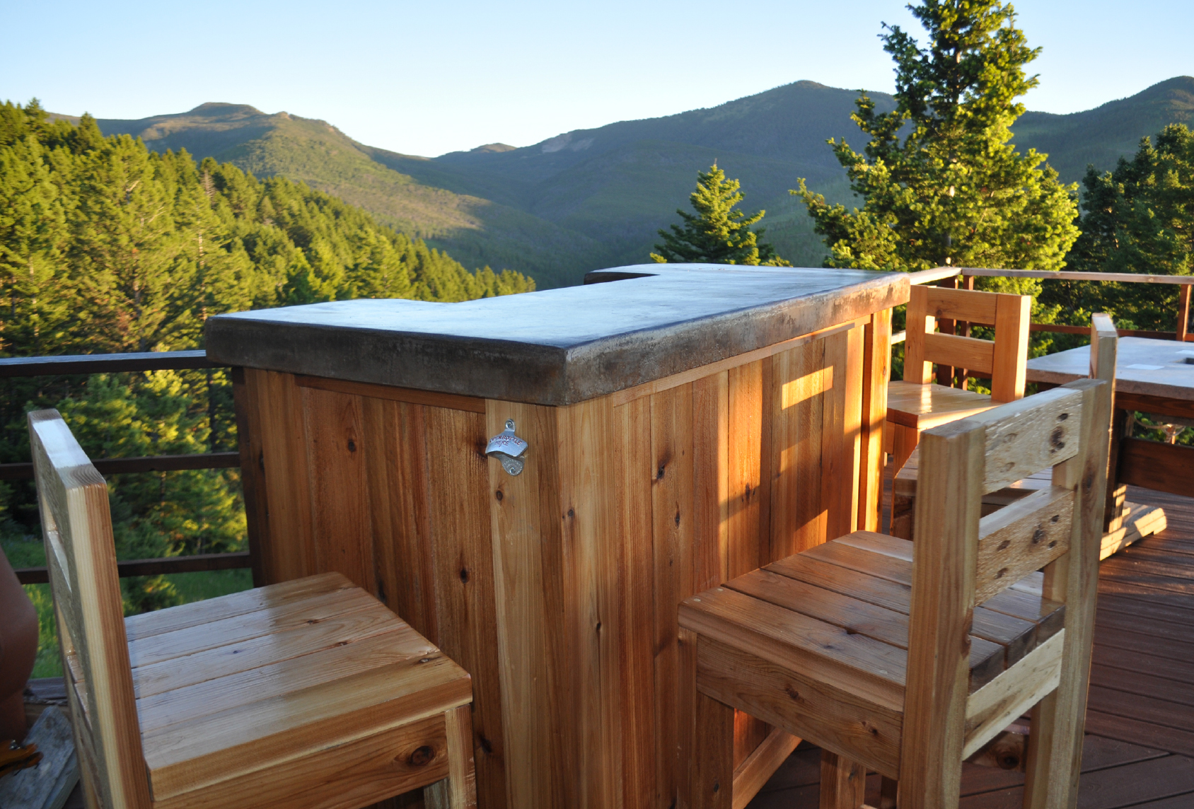
Patio Bar

Concrete Top


Materials List:

  • (1) – 4×8 sheet of melamine
  • (2) – 2×4 piece of 1 ½ inch thick foam
  • (1) – 1 box of 1 ½ inch screws and drill bit
  • (1) – 1 tube of silicon caulk
  • (1) – 4×8 sheet of square wire re-enforcement
  • Packing tape
  • (4) – Bags of Quikrete Concrete Counter Mix or Quikrete 5000 Mix
  • Permanent Marker
  • Packing Tape
  • Spray bottles and 5 gallon bucket or hose for rinsing
  • Ammonia or baking soda
  • Acid stain
  • Concrete sealer
  • 400 grit sandpaper and sanding block
  • Knife to cut foam

Step 1:

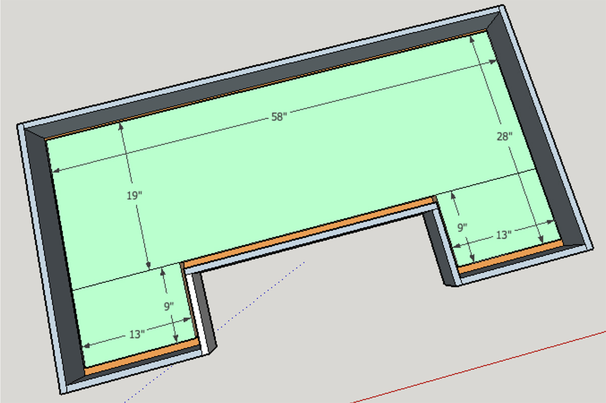
Build the mold for your concrete bar top. Cut ¾ inch thick melamine down to 60” wide by 30”. Then use a jigsaw to cut out the bartender area as seen in the diagram below.

Step 2:

Cut the strips for the sidewalls of your mold. The strips need to be 3 ¾ inches wide by the
dimensions shown in the drawing below. The strips will hold the concrete in and give you a
concrete top that is 3” thick around the outside perimeter of the piece.

Step 3:

Create the foam knockout using 1 ½ inch thick foam. Cut the foam using a sharp knife.
Foam is typically available in large 4 foot by 8 foot sheets or smaller 2 foot by 4 foot
sections. You can piece sheets together as needed to fit the space. Leave a 1 inch channel
around the perimeter of the foam. This will allow the concrete to form around the foam and make an apron. The concrete will look 3 inches thick around all sides. The rest of the
concrete will be 1 ½ inches thick which will reduce the overall weight of the finished bar
top.

Step 4:

Cut the steel re-enforcement to the same dimensions as the foam. The re-enforcement
should fit inside the mold with an inch of play on each side. Use a bolt cutter to cut the re-enforcement.

Step 5:

Fasten the foam to the base of the mold with silicon. Let dry and then mix up your concrete. I’d recommend Quikrete counter top mix or Quikrete 5000. Quikrete counter top mix will be much easier to get a nice smooth during the troweling process. The mix consists of smaller aggregate and additives that help increase the workability and strength of the concrete.

Step 6:

Allow the concrete to set-up. Once the concrete is firm, remove the sidewalls of the mold. If the concrete sags, quickly re-fasten the sidewalls and wait a little longer. When it is ready, fill in any voids with extra concrete and smooth it out using a small trowel. I’d recommend using a mixture with small aggregate for filling things in or making up your own mix of Portland cement, sand, and water

Step 7:

Hard trowel the top surface of the concrete. Use a 12” trowel. Please watch the video for
more tips and information about timing for the troweling process.

Step 8:

Allow the concrete to cure for at least 48 hours and then de-mold the entire piece. Sit the
concrete on wood blocks so the underside of the concrete will dry evenly. Let the concrete
cure for another 24 to 48 hours. Once cured, sand the entire piece by hand with 400 grit sandpaper.

Step 9:

Apply acid stain to the concrete using spray bottles or a pump sprayer. Read the directions
on your stain for more information. I typically recommend diluting the stain 1:1 with water. Allow the stain to sit for at least 8 hours. Then neutralize the acid by pouring a bucket of water on the surface that is mixed with baking soda or a very small amount of ammonia. Use a terry cloth to lightly clean the surface and remove extra residue. If this process is done too early you’ll remove some of the stain because it will not have had enough time to set in the concrete.

Step 10:

Allow the concrete to dry out for a few hours. Then use a water-based outdoor concrete
sealer to seal the concrete top. Apply 2 to 4 coats.

Step 11:

Install the concrete top on the base. First, run a bead of silicon caulk around the top of the
wood base to help prevent the concrete from ever sliding. It is very heavy so it won’t move once in place.

Step 12:

Install LED lighting if you’d like, fill up the cooler, and have your first barbecue! Then send
in a photo of your finished project. I’d love to see your new bar and share it with others to
help inspire more DIY’ers to build it!

Wood Base

Lumber:

  • (3) – 2x6x8 boards (Cedar)
  • (12) – (approximately) 2x4x8 (Cedar)
  • (1) – 4x4x8 (Cedar or Redwood)
  • (22) – 6ft long cedar pickets (siding, shelves, and trim)

Cut list:

  • (6) – 2×6 x 40” long (Corners and back or bar)
  • (4) – 2×4 x 40” long (Corners)
  • (3) – 2×4 x 54” long (frames)
  • (9) – 2×4 x 22” long (frames)
  • (2) – 2×4 x 35” long (frame)
  • (5) – 2×4 x 6 ½” long (frames)
  • (5) – 2×4 x 13” long (frames)
  • (1) – 2×4 x 11” long (frame)
  • (2) – 4×4 x 20 ½ long (frame)
  • (15) – 1×6 x 40” long pickets (siding) Approximate (Will need to rip at least 1 board)
  • (9) – 1×6 x 16” long pickets (shelving) May need to rip a few pieces
  • (6) – 1×6 x 23” long pickets (shelving) May need to rip a few pieces
  • (2) – 1×6 x 46” long pickets (rip to 3” wide) – Front top and bottom trim
  • (4) – 1×6 x 16 ½ inch long pickets (rip to 3” wide) – Side top and bottom trim
  • 1 box 2 ½ inch Kreg Screws
  • Outdoor grade wood glue
  • 1 box of 3 inch wood screws (exterior grade)
  • 1 box of 2 inch wood screws (exterior grade)
  • 1 box 1 ½ inch trim nails for a nail gun (optional)
  • 100 and 200 grit sandpaper for orbital sander
  • Four 3 inch or 4 inch caster wheels (I used 3 inch)
  • 16 2 ½ inch long leg bolts, washers, and nuts that are 7/16 in diameter

Step 1:

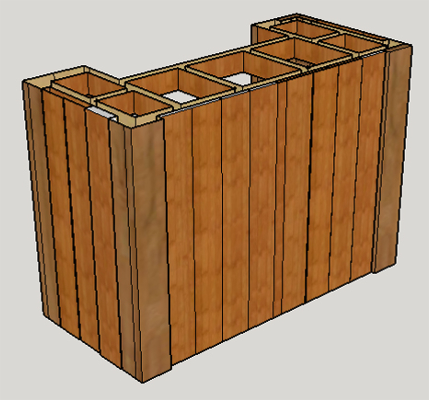
Assemble the top frame for the base. Make all your cuts and then assemble using 3 inch
screws. You could use a Kreg-Jig as well for some of the joints if you’d prefer. See the
diagrams below for measurements.

Step 2:

Assemble the lower frame. This is built out of 2×4’s and a 4×4 on each end. The 4×4
provides extra strength and surface area to mount the caster wheels to. Use 3 inch screws.

Step 3:

Create the front corners. Connect a 40 inch long 2×4 to a 40 inch long 2×6. A Kreg-Jig and 2 ½ inch screw work great for this process and eliminate screw holes around the outside of
the base. You could attach the boards using 3 inch screws at an angle if you do not have a
Kreg-Jig.

Step 4:

The rear corners consist of two 2×6 boards and one 2×4. All boards are 40 inches long. Use 2 ½ inch Kreg screws to connect the 2×6’s to each other.

Step 5:

Set the top frame on a flat surface and attach the corners/legs. Attach the corners to the frame using 2 ½ inch long wood screws. Use 3 or 4 screws in each board. Pre-drill pilot holes to minimize splitting.

Step 6:

Once the top frame and legs are attached you’ll want to flip the entire piece so it is right
side up. Them attach the lower frame to the corners/legs. Use a scrap ¾ inch thick scrap
boards to prop the lower frame up ¾ of an inch from the bottom of the legs. This will help
hide the wheels a bit and allow the siding to overlap the bottom 2×4.

Step 7:

Attach the 54 inch long middle support using 2 ½ inch long screws. Measure up 19 inches
from the top of the lower frame and make a mark. The top of the 54 inch long 2×4 should
line up with the mark

The middle shelves consist of 2x4s. Attach the 54” wide board first. Next attach the board
on the right, and finally the left side shelving.

Step 8:

Cut all the siding for the bar out of the 6 foot long cedar pickets. Cut approximately 15
pickets down to 40 inches. Next, measure and attach pickets to the lower and middle
frames to create shelves. Use 1 1/2 inch brad nails if you have an air gun. Or use 2 inch
screws and pre-drill if you do not have an air gun. The boards will be either 16 inches long
or 23 inches long. You may need to rip the end boards using a circular saw/table saw to
ensure a perfect fit.

Step 9:

Attach the cedar picket siding using an air gun and 1 ½ inch long nails. All boards should
be cut to 40 inch lengths. Use 3 on each end and 8 full boards on the front. I worked from
the outside in on the front and ripped the center board to fill the center gap.

Step 10:

Turn the bar on its side and attach the caster wheels if you haven’t already. Pre-drill and
use 2 ½ inch long 7/16 diameter leg bolts, along with a washer. Use 4 bolts and 4 washers
for each caster wheel.

Step 11:

Add trim to the top and bottom of the front and sides of the bar. Rip a couple pickets down
to 3 inches wide. The front trim will be approximately 46 inches long. Use an air nailer,
nails, or screws to attach each trim piece. The side trim will be approximately 16 ½ inches
long.

Step 12:

Run a bead of silicon around the top the base. Then find a few friends to help lift the
concrete into place.

Step 13:

Add a bottle opener and bottle cap catcher if you’d like. LED strip lighting can be ran along
the underside of the concrete which look neat when dark.

The original plan can be found at https://www.diypete.com

 
[email_link]


Outdoor Bar

Materials:

  • (2) Sheets 1/2”Plywood
  • (2) 4 x 4 x 96” Boards
  • (6) 2 x 4 x 96” Boards
  • (5) 1 x 6 x 96” Boards
  • Carpenter’s Wood Glue
  • 1” & 1 ¼” Brad Nails
  • 1” & 2 ½” Pocket Hole Screws
  • 2 ½” Wood Screws

Cut List:

Plywood:

  • (1) Top @ 21 x 50”
  • (1) Front Panel @ 41 x 42

4×4’s:

  • (4) Legs @ 41”

2×4’s:

  • (4) Long Frames @ 42
  • (4) Short Side Frames @ 13”
  • (8) Supports @ 15 ¼”
  • (2) Long Middle Supports @ 34”
  • (4) Shelf Braces @ 19 ¼”
  • (2) Side Panels @ 13 x 34”
  • (2) Shelves @ 15 ¼ x 42”

1×6’s, Cut one 1×6 into ½” trim:

  • (2) ½ x ¾ “ top trim @ 21”
  • (2) ½ x ¾ “ top trim @ 51”
  • (2) ½ x ¾ “ front trim @ 40 ½”
  • (2) ½ x ¾ “ front trim @ 41”

Step 1:

Build frames by first attaching your short side frames to the legs of the bar with 2 ½” pocket hole screws and wood glue. Next, attach your long frame pieces using the same method of joinery.

IMPORTANT: make sure to include pocket holes in all top frame pieces that are facing up for attaching the top panel later!

Step 2:

Add the side panels with pocket hole screws and wood glue.

Step 3:

Attach the long supports/large frame pieces with 2 ½” pocket hole screws and wood glue.

Step 4:

Attach your shelving braces with 2 ½” pocket hole screws and wood glue.

Step 5:

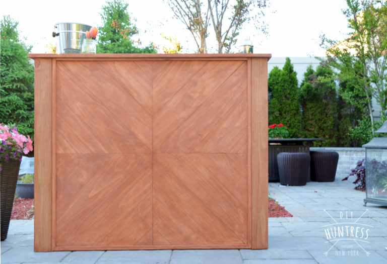
Prep your front panel for artwork! Use a pencil and a straight edge to split your front panel into four equal sections. This will help with lining up your pieces in the next step.


Step 6:

Begin attaching 1×6 pieces. This is done by cutting one end of a 1×6 board at a 45 degree angle and lining it up with the middle intersection you made with your pencil. You can either mark the cut that overhangs at the end here (and trim your pieces as you go), or you can cut your pieces a little long and trim the entire panel down later. Work in one section at a time to avoid mistakes! Use a nail gun and glue to hold your boards down.

Step 7:

Once your panel is complete and the sides are flush, attach it to the front of the bar by screwing and gluing it onto the frames from the inside. This will hide the wood screws on the inside of the bar.

Step 8:

Begin adding your supports to help hold the weight of the shelves and the top (top supports not shown in image below). Attach these to the frames with 2 ½” pocket hole screws and wood glue.

IMPORTANT: In order to make your shelving panels lay flush with the shelving frames, you will have to install your shelf supports ½” (or the equivalent width of your plywood) below the top of your frame pieces. In other words, leave a ½” gap at the top of your supports for the shelf to drop in later.

Step 9:

Drop your shelving panels into place and secure them to the supports with 1” brad nails and wood glue.

Step 10:

Install your top panel with 1 ½” pocket hole screws and wood glue from the bottom frame.

Step 11:

Attach ½ x ¾” trim pieces cut from your 1×6’s to the front panel (@ 41”and 42” — to hide any imperfect gaps – this is optional!) and the top (@ 23” and 51” — to hide the plywood edging).

Step 12:

Sand and then stain and seal your bar with outdoor/waterproofing sealer or stain!

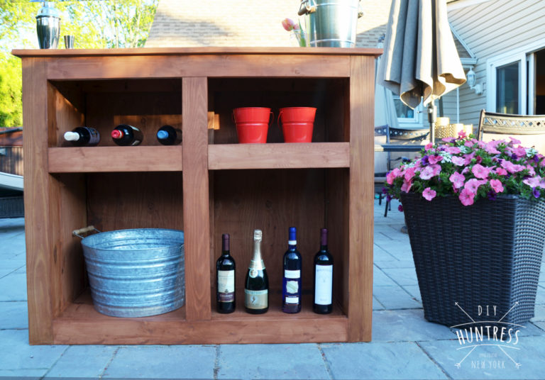
The original plan can be found at http://diyhuntress.com

 
[email_link]

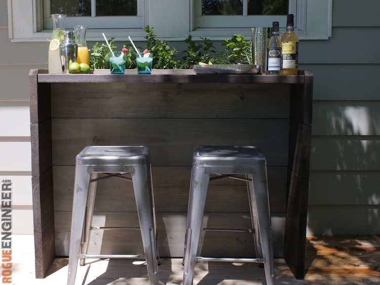
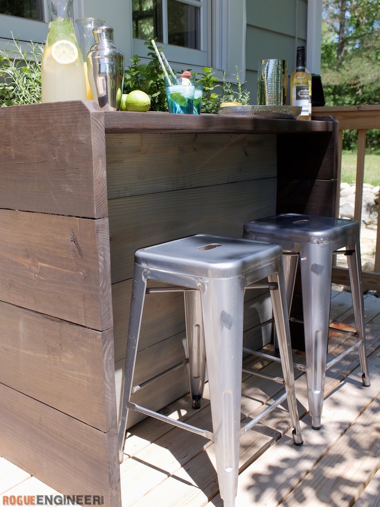
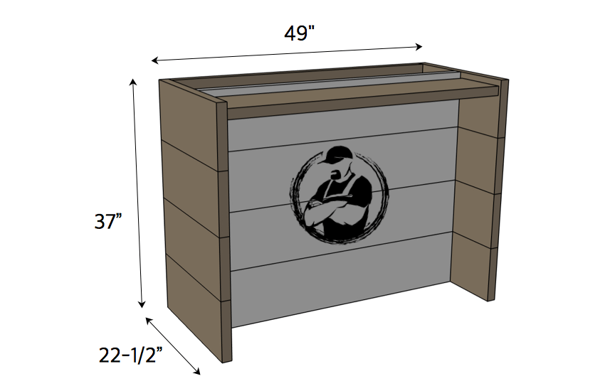
Cocktail Garden Bar

Materials:

  • (6) – 2 x 10 x 8′ Pressure Treated
  • (1) 2 x 4 x 8′ Pressure Treated
  • 2 1/2″ HD Pocket Screws
  • #20 Biscuits
  • Wood Glue

The original plan can be found at https://rogueengineer.com

 
[email_link]
 

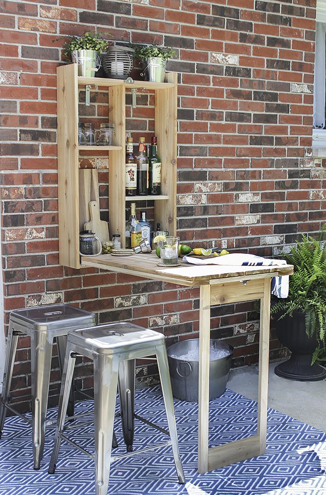
Murphy bar


Step 1: Cut the Wood to Size

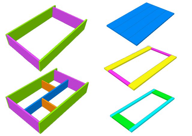
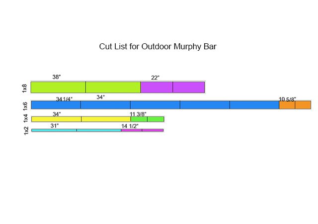
In the illustrations below, you will see the five different phases of what you will be building as well as the cut list for the various wood pieces. You will need to cut:

  • 2 pieces from the one-by-eight at 38 inches
  • 2 pieces from the one-by-eight at 22 inches
  • 1 piece from the one-by-six at 34 1/4 inches
  • 4 pieces from the one-by-six at 34 inches
  • 2 pieces from the one-by-six at 10 5/8 inches
  • 2 pieces from the one-by-four at 34 inches
  • 2 pieces from the one-by-four at 11 3/8 inches
  • 2 pieces from the one-by-two at 31 inches
  • 2 pieces from the one-by-two at 14 1/2 inches


Step 2: Build the Box Frame

Use the four one-by-eight pieces to create the box frame. Using the pocket hole joinery system, drill three 3/4-inch pocket holes on either end of the short one-by-eight pieces (top and bottom), about 2 inches apart. Make sure to drill the pocket holes on the rough side of the board. Attach the bottom piece first, flush with the side pieces, using 1 1/4-inch pocket hole screws and wood glue. Then attach the top piece, 3 inches down from the top of the sides, using the same method as the bottom piece. Be sure to wipe up any excess wood glue with a damp rag. The opening between the top and bottom piece should be 34 1/4 inches.


Step 3: Attach the Divider Shelves

Drill two evenly spaced 3/4-inch pocket holes on either end of the long divider one-by-six board. Measure the center mark at 11 inches on the top and bottom of the box frame and make a line all the way down using a speed square. Line the one-by-six board up so the top and bottom marks are at the center of the one-by-six, and then attach it to the box frame using 1 1/4-inch pocket hole screws and wood glue. For the shelves, place the short one-by-six pieces to your desired heights and attach them on either side of the divider with an electric nail gun and 1 1 /4-inch nails. In this project, the lower shelf was attached 1 foot from the bottom and the upper shelf 11 inches from the top.


Step 4: Build the Planked Tabletop

The top of the fold-out bar will be built with four one-by-sixes. To attach them together, drill five 3/4-inch pocket holes evenly spaced on the rough side of three of the boards. Assemble them flush together so the rough side is facing up, with one of the boards in the middle not having any pocket holes drilled. If needed, step on the top of the boards as you screw them together using 1 1/4-inch pocket hole screws and wood glue, so as to keep the top flat. Work slowly and don’t over-screw into the wood, as you don’t want the screws to poke out of the other side. This is where you can choose to use the optional 1-inch pocket hole screws instead, so as to not risk the screws coming out of the other side.


Step 5: Build the Support Frame for the Tabletop

Drill two 3/4-inch pocket hole screws on either end of the 14 1/2-inch one-by-twos. Assemble the one-by-twos and the 34-inch one-by-fours on top of the tabletop planks you just screwed together so that the one-by-fours are flush with the long edge and the one-by-twos are flush with the short edge. This is so you make sure the sizes are exactly the same. Use clamps and wood glue to attach the one-by-twos flush on either end of the one-by-fours, making sure the rough sides are facing up. Note: you are not actually attaching the support frame pieces to the tabletop in this step.


Step 6: Attach the Support Frame to the Tabletop

Flip the support frame over so the rough side with the pocket holes is facing down toward the rough side of the tabletop. Put wood glue between them and then attach the frame to the tabletop using a nail gun and 1 1/4-inch nails.


Step 7: Assemble the Fold-Out Leg Frame

Drill two 3/4-inch pocket holes on either end of the shortest one-by-fours. Place the 31-inch one-by-twos inside the support frame along both long sides and the short one-by-fours on either side of the short sides, with the rough sides facing up. On one end, allow a small gap between the one-by-four of the leg frame and the one-by-two of the tabletop support frame so the 2-inch hinges will fit. Keep the hinges there while you attach the leg frame pieces together using 1 1/4-inch pocket hole screws, making sure to put wood glue between the joints first. Note: you are not actually attaching the leg frame pieces to the tabletop in this step.


Step 8: Attach Hinges to the Leg & Support Frames

Flip the leg frame over so the rough side is facing the rough side of the tabletop. Measure and mark with a pencil or pen where the position of the hinges will be to join the leg frame and support frame. In this project, the hinges were positioned 1 inch from the edge of the one-by-four of the leg. Pre-drill holes where you made the marks and attach the hinges with the provided screws.


Step 9: Attach Hinges to the Box Frame

Place the tabletop with legs attached on top of the box frame. Orient the tabletop so the planks are facing inward and the bottom of the legs are closest to the bottom of the box frame. Push the bar up, allowing a small gap to form at the bottom where the hinges will be placed. Slide the 4-inch hinges in between the one-by-four of the support frame and the edge of the box frame. Mark the location of the holes with a pencil or pen. Pre-drill the holes and then attach the hinges with the screws provided.


Step 10: Attach a Half-Turn Button for the Leg

Once the hinges are attached, you might notice the bottom of the leg pops out a little bit and doesn’t fit flush (see photo in Step 9). To keep the leg flush, you will need to install a half-turn button on the one-by-two of the support frame that it touches. Measure the middle mark on the one-by-two, pre-drill a hole, and screw in the galvanized half-turn button. Don’t tighten it all the way, so the button can move over the bottom of the leg and keep it flush with the rest of the unit.

Step 11: Attach a Sash Lock to the Box Frame

Using the pre-marked 11-inch center on the box frame, mark where the screw holes will be on the box frame for the sash lock. Align the other side of the sash lock on the one-by-two of the support frame and mark where the screw holes are. Pre-drill holes and attach with the screws provided.


Step 12: Attach the L-brackets

On the the inside of the box frame, at the top, center on either side of the opening where the 4-inch L-brackets will be attached, and mark with a pencil or pen. Drill the four holes (two on each bracket) with a 1/4-inch drill bit. Attach the 4-inch L-brackets with the 1/4-20 bolts and corresponding size wing nuts, so the wing nuts attach on the inside. Repeat the process on the bottom of the box frame using the smaller 2-inch L-brackets, attaching the wing nuts on the underside. This keeps the inside surface usable. You can also countersink the bolt, so it doesn’t stick up at all. The top L-brackets hold the weight of the bar and the bottom ones just keep it sturdy.


Step 13: Mount the Bar on an Exterior Wall

Have a helper position the Murphy bar so the base of the unit is 32 inches off the ground. Mount the murphy bar in your desired location, using 3-inch exterior wood screws if you have wood or vinyl siding, or 1 1/2-inch stainless steel brick screws with lead anchors, pre-drilling the holes first.

This outdoor Murphy bar is the perfect size to prepare cocktails and drinks for an evening get-together…

…or you can stock it with seasonings, sauces and grilling utensils as the perfect prep and serving station for an outdoor grill.

The original plan can be found at https://www.hunker.com

 
[email_link]
 

Moreno Bar

Materials:

  • 1 – 1×2 at 6’
  • 2 – 1×3 at 8’
  • 3 – 1×4 at 8’
  • 1 – 2’ x 2’ sheet of ¼” plywood, lauan, or hardboard
  • 1 – half sheet of ¾” plywood
  • 1 – full sheet of ¾” plywood
  • 1-1/4” pocket hole screws
  • 1-1/4” screws
  • 1-1/4” brad nails
  • 1” brad nails
  • Edge banding for the plywood
  • 1 set of 16” drawer slides
  • 3 – Cabinet pulls
  • 2 sets of hinges for the doors
  • 1 set of hinges for the flip-up top
  • 2 Friction Lid Supports

Cut List:

  • 4 – 1×4 (ripped to 2-3/4” wide) at 33-1/4” – Side Legs
  • 2 – ¾” plywood at 10-3/4” x 30-3/4” plywood – Side Panels
  • 2 – 1×4 at 29-3/4” – Front Legs
  • 1 – 1×4 at 45” – Front Stretcher
  • 1 – ¾” plywood at 34-3/4” x 43-1/2” – Back
  • 3 – ¾” plywood at 15-1/2” x 43-1/2” – Shelves
  • 1 – 1×3 at 27-1/4” – Front Divider
  • 1 – 1×4 (ripped to 2-3/4” wide) at 15-1/2” – Top Divider
  • 1 – ¾” plywood at 12-1/8” x 16-3/4” – Fixed Top
  • 1 – ¾” plywood at 16-5/8” x 33-3/4” – Flip-Up Top
  • 4 – 1×3 at 12-1/2” – Door Frame

Step 1:

If using edge banding, it will be applied to the exposed edges of the plywood before assembly. Cut the pieces for the side legs and the side panel. Cut the angle in the leg using a jigsaw. Set the Kreg jig for ¾” material and drill pocket holes in each long end of the panel, and in one long edge of one leg as shown. Keep in mind, there will be a right side assembly and a left side assembly! Attach the legs to the panels using glue and 1-1/4” pocket hole screws.

Step 2:

Cut the pieces for the front legs and the front stretcher. Cut the angle in the legs using a jigsaw, and drill pocket holes in the top edge keeping in mind there will be a right and a left. Cut the hole in the stretcher for the drawer using a jigsaw. Attach the legs to each end of the stretcher using glue and 1-1/4” pocket hole screws, then attach the side panels using glue and 1-1/4” pocket hole screws through the holes drilled in the side legs.

Step 3:

Cut the piece for the back. Draw a 4” radius at each corner and cut with a jigsaw. Drill pocket holes in each side edge. Secure the back piece to the sides using glue and 1-1/4” pocket hole screws. The back will stand 4” above the side to create a “backsplash”.

Step 4:

Cut the pieces for the shelves and drill pocket holes in three edges. Secure to the cabinet as shown using glue and 1-1/4” pocket hole screws. The bottom of the upper shelf will be flush with the bottom of the upper stretcher.

Step 5:

Cut the piece for the front divider and drill pocket holes in the top edge. Secure to the upper stretcher as shown. Add a couple of countersunk 1-1/4” screws through the divider into each of the shelves.

Cut the piece for the top divider and drill pocket holes in each end. Position as shown and secure using glue and 1-1/4” pocket hole screws.

Step 6:

Cut the piece for the fixed top. Position the piece so that it butts up against the backsplash and overhangs the front and side by ½”. Secure in place using glue and 1-1/4” brad nails.

Cut the piece for the flip-up top and install the hinges. There will be a 1/8” gap between the top and the back splash as well as between the top and the fixed top. The front and sides will overhang by ½”.

Step 7:

Cut the pieces for the doors and drill pocket holes as shown. Install the hinges, then install the doors. Attach the cabinet pulls in the location desired.

Step 8:

Cut the pieces for the drawer. Drill pocket holes in each end of the side pieces, and assemble the frame using glue and 1-1/4” pocket hole screws. Attach the bottom using glue and 1” brad nails. Install the drawer slides according to the manufacturer’s instructions. Make any necessary adjustments.

Cut the piece for the drawer front. Install the cabinet pull as desired.

Fill any Screw, Nail or Pocket Holes, Sand and Finish as Desired.

The original plan can be found at http://www.thedesignconfidential.com

 
[email_link]

Cedar Bar

One of the most useful items for a deck or patio is a large flat area where you can prepare and serve food, pour hot or cold drinks, and have adequate storage for these tasks close at hand. This cedar bar is designed to provide you with the convenience of both storage and a work surface at a convenient height. The top of the bar can be separated from the shelving unit for storage if necessary, by removing two screws. We designed the storage area to accommodate a medium-sized cooler, but the cleats for the shelving can easily be altered to adapt to your particular needs.

Material:

  • (48 ft.) 1 x 6 Cedar
  • (42 ft.) 5/4” Cedar
  • (32 ft.) 2 x 4 Cedar
  • 3” deck screws
  • 1 ½” deck screws
  • Finishing/cup washers
  • 5/16” Hardwood buttons

Parts:

  • (4) 5/4” x 3 ½” x 41” – A – frame legs – front/back
  • (4) 5/4” x 3 ¼” x 41” – B – frame legs – sides
  • (4) 2 x 4 x 48” – C – frame front & back
  • (4) 2 x 4 x 15” – D – frame sides
  • (2) 2 x 4 x 31” – E – top frame
  • (2) 2 x 4 x 53 ½” – F – top frame
  • (2) 1 x 4 ½” x 39” – G – front cladding – end pieces
  • (10) 1 x 6 x 39” – H – front & side cladding
  • (8) 1 x 6 x 18 ¼” – I – floor boards
  • (1) 2 x 4 x 15” – J – brace
  • (1) 5/4” x 1 ¾” x 18 ¼” – K – cleat – floor
  • (2) 5/4” x 6” x 33” – L – vertical shelf supports
  • (3) 5/4” x 1 ¾” x 16 ½” – M – mid shelf cleats
  • (3) 5/4” x 1 ¾” x 18” – N – outer shelf cleats
  • (6) 1 x 6 x 22” – O – shelves
  • (3) 1 x 6 x 24 ¾” – P – shelves
  • (5) 1 x 6 x 50 ½” – Q – top boards

Steps:

Cut all the pieces referring to the diagrams. At all screw locations, use a #8 screw setter bit to countersink the deck screws, and use 1 1⁄2″ galvanized nails to avoid weather staining of the wood surface. Use exterior wood glue when nailing or screwing components together.

Build the two end frames. Begin with the corners, using 3″ deck screws and glue. Join the sets of corners/legs with the upper and lower frame pieces to complete the end frames. Use a carpenter’s square to ensure square corners.

Complete the bar frame by fastening the front and back frame pieces to the end frames as shown, using 3″ deck screws and glue. Clamps may be useful here, as well as a carpenter’s square to again check for square corners. Set the bar frame aside to allow the glue to set.

Build the top outer frame, mitre the corners, and fasten with 3″ deck screws and glue. Be sure the frame is square.

Fasten the cedar cladding to the front and two end sections of the bar frame using 1 1⁄2″ nails and glue. Plane or cut the rounded edge off the two outer front boards. This will allow for some spacing between the eight front boards, and tight flush corners. Space the two boards for the side sections as shown.

Fasten the floor boards to the frame using nails and glue. Install the 2″ x 4″ piece in the upper frame, and the cleat on the floor as shown, then fasten the two vertical shelf support boards to them.

Install the six additional shelf support cleats using 1 1⁄2″ deck screws and glue.

Set the shelf pieces on the cleats. You may wish to alter or add shelves to serve your particular needs or choice of storage.

Place the five boards into the top frame, and secure with 3″ deck screws and glue. Trim or plane the two outer boards on one edge to provide a tight edge with the top frame.

Sand all surfaces and apply a sealer or wood stain as directed on the container.

When the sealer is dry, set the bar top on the lower section, and secure with two 3″ screws in cup washers as shown.


The original plan can be found at http://www.homeathome.homehardware.ca

 
[email_link]
 

Boat Shaped Bar

I have a long list of projects to tackle before I hang up my tool belt for good. And near the top of this list is a boat. Although this rowboat-shaped bar will never leave the shore, its construction is similar to building the real thing in many ways. You need thin wood for many parts of this project, both to keep weight down and to allow the wood to bend. That’s why I chose a marine favourite to build the bar: cedar.

Click to enlargen

Cut List:

  • (13) 1/2″ x 1 3/4″ x 80″ Cedar – Back panel strips
  • (3) 3/4″ x 13 3/4″ x 36″ Cedar – Lower bulkheads
  • (1) 3/4″ x 11 3/4″ x 22″ Cedar – Shelf bulkhead
  • (1) 3/4″ x 9″ x 14 1/2″ Cedar – Bow bulkhead
  • (2) 3/4″ x 4″ x 24 1/4″ Cedar – Door opening stiles
  • (2) 3/4″ x 3 1/2″ x 33″ Cedar – Front/rear base frame rails
  • (2) 3/4″ x 3 3/4″ x 12 1/4″ Cedar – Base frame side rails
  • (2) 3/4″ x 9″ x 5 1/2″ Cedar – Upper/lower bow plates
  • (2) 3/4″ x 5 1/2″ x 13″ Cedar – Vertical center support ribs
  • (4) 1/4″ x 5 1/4″ x 87″ Cedar – Lower and center side panels
  • (2) 1/4″ x 5″ x 87″ Cedar – Upper side panels
  • (2) 1/4″ x 1 1/2″ x 15″ Cedar – Nose trim
  • (6) 1/4″ x 3/4″ x 86″ Cedar – Gunwale strips
  • (1) 1/2″ x 10″ x 10″ Cedar – Decorative bow plate
  • (4) 3/4″ x 2 1/2″ x 8 1/2″ Cedar – Door rails
  • (4) 3/4″ x 2 1/2″ x 24 1/8″ Cedar – Door stiles
  • (2) 1/4″ x 9 1/2″ x 20 1/8″ Cedar – Door panels
  • (10) 3/4″ x 1″ x 13 3/4″ Cedar – Wine storage cleats
  • (5) 1/4″ x 5 1/4″ x 13 3/4″ Cedar – Wine storage partitions
  • (5) 3/4″ x 1″ x 11 1/2″ Cedar – Stemware spacers
  • (3) 1/4″ x 3 1/4″ x 11 1/2″ Cedar – Wide stemware rails
  • (2) 1/4″ x 2″ x 11 1/2″ Cedar – Narrow stemware rails
  • (4) Brass hinges
  • (2) Dock cleat pulls – brass

Getting Started:

Begin by making a rectangular blank for the back panel of the bar, which consists of 13 narrow slats brought together with splines. Cut the slats to size, then use the tablesaw to rip a 1/4″-deep x 1/8″-wide slot along the adjoining edges to receive the splines. You’ll find tips for creating spline joints on next page.

Normally, I use bar clamps to secure large panels such as these; but in this case, the force is likely to cause the thin panel to buckle. You could prevent this by clamping cauls on the top and bottom, but there’s an easier way. Simply stretch celluloid packing tape across the face of the panel at regular intervals. Just be sure to tape both sides or the assembly will cup in the centre. After the glue sets, remove the tape and sand both sides of the panel smooth.

Next, lay out the curved sides and the locations of the horizontal bulkheads. Start by scribing a line down the centre of the panel, running in the same direction as the slats, then measure out from this centre line to mark the point at which the bottom corner of each bulkhead meets the curved sides. All the measurements you need are shown on the plans (see following pages).

Drive a 1 1/2″ spiral finishing nail at the end of each bulkhead location, leaving the head protruding from the top surface of the panel. You’ll also need to drive a nail in the bottom corners and where the sides meet at the bow. Next, cut a long strip of wood from thin material and bend it around the outside of the nails to form a gentle curve on one side of the boat. Scribe a pencil line along the inside edge of this strip. It’s good to have a couple of helpers to complete this procedure, but you can handle the job yourself by securing the wood strip to the nails with spring clamps. Repeat the entire process to prepare a mirror image of the curved profile on the opposing side. Before removing the nails, use a straightedge and a pencil to mark the bottom edges of the bulkheads. When this is done, pull all the nails and, following the pencil lines at the sides with a jigsaw, cut the back panel to shape.

Building the bulkheads:

Unless you have some wide stock on hand, you need to edge-glue boards to create five wide panels for the bulkheads. As part of completing my glue-ups, I installed a few #20 biscuits to help with alignment. Note that the measurements given in the materials list for these parts includes a waste allowance for trimming panels to length. This is important because the ends need to be cut at an angle to match the curved shape of the back panel on your particular project. To determine where to cut, simply mark the ends while holding the bulkheads on edge. The reference lines you made earlier tell you exactly where to position the bulkhead when you do this operation. Take the bulkhead panels over to the tablesaw and adjust the blade to the angle of the reference lines. Make a test cut about 1/8″ on the waste side of the mark to verify the blade is positioned correctly. If the cut is parallel to the line, you know you have it right.

When you’re satisfied, make your cut right to the line. The angles will be different for each panel, so mark and trim each end individually.

Strengthening the Structure:

Set aside the bow bulkhead and glue the rest on edge to the face of the back panel. You can hold these bulkheads in place with clamps, or tack them in position through the back panel with an air nailer or spiral finishing nails.

Take a look at the plans to see how the door stiles extend between the lower bulkheads to square up the opening for the doors. To make these parts, cut out a pair of rectangular blanks, then use the sides of the back panel as a pattern to lay out the curved edges. When you trace the profile, position the inside edge of the blanks 13 5/8″ from the back panel’s centre line. This location corresponds to the sides of the door opening. After transferring the profile to the blanks, head over to the bandsaw to complete the cuts. Sand the edges, then install the stiles flush with the front inside edges of the bulkheads using a couple of dowels to connect the ends into the bulkheads.

Next, turn your attention to the frame that supports the base of the bar. First, cut out rail blanks for the front and rear of this frame. Once again, you’ll use the back panel as a pattern to transfer the profile to the ends of the rails before trimming them to length with a bandsaw. After sanding, glue the rear piece directly to the back panel and attach the front to the underside of the lower bulkhead with glue and #20 biscuits.

Cut out blanks for the base frame side rails as well. Prior to installation, you’ll need to bevel the top and bottom edges of the side rails at the tablesaw to compensate for the slope of the side of the back panel. For my project, I needed 10º angles, but you should use an angle gauge to check yours. There could be variation in the profile of your back panel. Apply glue to the ends and the top edges of the frame sides, then clamp the parts in place.

Now that you’ve reinforced the stern, it’s time to build the bow. Grab the short bulkhead you made earlier and prepare blanks for the triangular upper and lower bow plates. As before, use the back panel as a template to trace the side profile onto the blanks and cut out the shapes at the bandsaw. Attach the bottom edges of the plates perpendicular to the top and bottom of the short bulkhead with glue and biscuits.

Next, prepare the centre support ribs that stand vertically between the bow plates. Start by laminating a double thickness of 3/4″ material to make the blank, then bevel the edges at the front to create a point that matches the tip of the bow plates. Apply glue to the top and rear edges of the joined ribs and clamp the assembly in place, with the back edge centred against the upper bulkhead. Finally, glue the entire bow assembly to the top of the back panel.

Side step

You need to strengthen the structure of the hull by connecting the bulkheads to the side panels. Each side comprises three wide strips, secured with lap joints along their mating edges. Start by preparing 1/4″- thick material for the panels using one of the resawing techniques on page 66. Rip the strips to final width and mill the 1/8″-deep x 1/4″-wide rabbets along the edges to form lap joints. Make them at the router table with a straight bit or by using a dado blade in the tablesaw.

To make this installation easier, find an extra pair of hands to help, and conduct a dry-fit before you reach for the glue. I recommend an air-powered finishing nailer as the easiest way to tack the strips to the sides of the hull while the glue dries. The curved shape makes it difficult to get a solid grip with bar clamps. Hammerdriven finishing nails installed close to the edge of the thin material may cause the wood to split.

Adding doors and compartments:

Begin by installing one of the side strips that touches the back panel. Start fastening it at the bow and tack it to the edge of the bulkheads and back panel as you progress downward. These strips are longer than necessary to allow for a slight overhang at the bow and stern.

After you’ve attached all three strips to one side, grab a handsaw and trim the excess material from the ends before repeating the entire process on the opposing side. Don’t be concerned if there’s a gap where the two sides meet at the bow. You’ll cover this with nose trim. To make this trim, cut out the two 1 1/2″- wide trim strips from 1/4″-thick material and bevel the top edges to form a corner where the two pieces meet. After gluing the strips in place, perform a nose job by rounding over the sharp point with a sanding block, creating a softer, slightly weathered appearance.

All the trimmings

The next task is to build up the top edges of the gunwales (the thick ridge along the top edge of each side) by adding several layers of 3/4″-wide x 1/4″-thick trim strips. For this job, you’ll need to gather as many small clamps as you can find around the shop. Also, install only one strip at a time to make the job more manageable. To apply the strips, coat one side with glue, then work from bow to stern as you clamp the trim to the gunwale. Check for gaps and make sure the outside edges are aligned before allowing the glue to dry.

Apply one layer to the outside and two more following the interior curve. The strips start from the top bulkhead on the inside and one strip goes from the nose trim on the exterior. Like the side panels, the strips are longer than needed. Simply saw off the excess at the stern when you’re done. After the last strip is applied, sand the outside faces of the lamination and roundover the corners.

With the gunwale complete, make the decorative bow plate that covers the bow structure. Cut out a blank from 1/2″-thick material, trace the shape of the bow to lay out the sides, and use the grid diagram in the plans to outline the design for the decorative bottom edge. Cut out the shape on your bandsaw, sand and roundover the top edges with a router spinning a 1/4″-radius bit. After you glue the plate in place, sand the sides to blend the edges of the cap with the outside of the gunwale trim.

Open and shut

With the basic structure of the boat bar complete, you’re ready to add doors to the lower compartment. These are simple frames that capture floating solid-wood interior panels. Start by edge-gluing 1/4″-thick material to make the panels. This is one more opportunity to practise the resawing techniques below.

Next, cut out the vertical stiles and horizontal rails. Mill 1/2″-deep x 1/4″-wide grooves along the inside edges to receive the panels. Don’t change the set-up-you also need to make slots of the same size on the ends of the horizontal rails. These receive wood splines that reinforce the corner joints. Cut out some splines from scrap and you’re ready to assemble the doors. When you do, apply glue to the end of the rails and both sides of the splines, but keep the panel slots dry. The panels need to float freely in grooves to allow for seasonal expansion and contraction.

Install the panels and bring the frame members together with splines and clamps. Check for square before setting the doors aside to dry. I used some decorative brass hinges to mount the doors and found decorative brass dock cleats at my local building centre to use as door handles.

Accessorizing and finishing touches:

A bar is not complete without a place to keep wine bottles. I included plenty of storage for these in divided compartments located directly under the bar top. Start by preparing cleats with 1/4″-wide x 3/8″-deep slots to receive the storage partitions. For a more pleasing appearance, chamfer the sides and fronts of the cleats with a router and 45º bearing guided bevelling bit before gluing them into place. When you install these parts, make sure the upper and lower cleats are aligned to ensure the divided openings end up being square. The storage partitions are made from 1/4″-thick material. The only fancy thing about them is the concave decorative curve I cut on the front edges. The partitions slide into place with no glue so they can be removed for finishing.

Another touch is to add a place to hang your stemware. Cut out the spacers and rails as shown in the materials list, then glue the rails to the spacers with an equal overhang on both sides. The narrow rails, located on the ends, overhang the spacers only on the inside edges. Drill pilot holes and screw the assemblies to the underside of the shelf bulkhead.

Start from the centre and work your way out to the sides, making sure to maintain a consistent 3/4″ gap between the rails. Use a scrap spacer to eliminate the need to measure and help you to achieve more consistent results.

Final finishing

To finish my bar, I chose to go with a natural look by applying a tinted exterior wood preservative Thompson wood protector in sheer honey gold. This step slows the greying process that occurs with any wood after extended exposure to the sun. Another option is to apply a distressed paint finish that simulates years of weathering at sea.

If you plan to use the boat bar outdoors, anchor the top to a fence or wall to prevent it from toppling over. Now you can grab a glass and make a toast to the maiden voyage of your new bar.

The original plan can be found at http://canadianhomeworkshop.com

 
[email_link]

Wet Bar

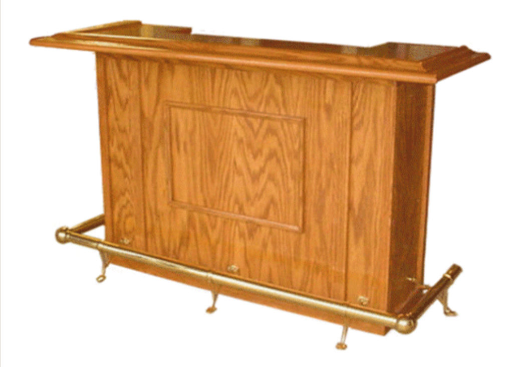
Entertain your friends in style with this beautiful oak bar. The top is 6 ft. long and 24” deep. The overall height about 42”. The classic design features solid oak armrest molding, solid brass foot rail, a convenient work shelf in the rear, three drawers, and two sliding wine racks. The cabinet is made of ¾” oak veneered plywood. The trim and drawer fronts, from ¾” solid oak. The extensive use of pocket holes makes the assembly of this project easy and intuitive. If you have never used pocket holes in your woodworking projects, you’ll wonder how you ever got by without them. Pocket hole joints are extremely strong and there is no measuring. You simply drill the pocket holes in one of the work pieces to be joined, (the exact location is not critical), clamp the pieces together and insert the screws. Since the screws remain in the joint, they serve as both a dowel and a permanent clamp.

Materials:

  • (2) Sheets of Pine plywood
  • (1) Sheet 3/4″ Oak Veneer Plywood
  • (1) Sheet 1/2″ Oak Veneer Plywood
  • (1) Sheet 1/4″ Hardboard
  • (4) 5 1/2″ x 8′ x 3/4″ Oak boards
  • (1) 6 1/2″ x 8′ x 3/4″ Oak boards
  • (1) 4′ length of Oak Armrest moulding
  • (1) 6′ Length of Oak Armrest moulding
  • (1) 6′ length of 2″ dia. polished brass foot rail
  • (1) 4′ length of 2″ dia polished brass foot rail
  • (5) Polished brass floor brackets
  • (2) 2″ dia polished brass elbows
  • (2) 2″ dia. polished brass end caps
  • (5) 14″ drawer slide sets
  • (3) drawer handles
  • 1 1/4″ Pocket hole screws
  • 1″ Flathead wood screws
  • 1″ Finishing nails
  • 1 1/2″ Finishing nails
  • (7) Small Angle brackets

Building the Cabinet

Cut List:

3/4″ Plywood

  • (2) 6 1/2″ x 41 1/8″ – Left/Right Front Panels
  • (1) 41″ x 41 1/8″ – Center Front Panel
  • (2) 14″ x 41 1/8″ – Cabinet Sides
  • (2) 14″ x 23 1/2″ – Vertical Dividers
  • (2) 14″ x 52 1/2″ – Top Work Shelf/ Bottom
  • (1) 5″ x 52 1/2″ – Kick Panel
  • (1) 16″ x 14″ – Small Shelf
  • (15) 14″ x 2″ – Cleats
  • (2) 19″ x 2″ – Front Cleats

3/4″ Oak Boards

  • (2) 2″ x 55 1/2″ – Top/Bottom Trim (front)
  • (2) 2 1/2″ x 36″ – Fluted Trim (Front)
  • (4) 1 1/2″ x 36″ – Corner Trim
  • (2) 3/4″ x 36″ – Side Corner Trim (Front)
  • (4) 2″ x 16 1/4″ – Top/Bottom Trim (Side)
  • (2) 1″ x 26″ – Decorative Frame (Top/Bottom)
  • (2) 1″ x 18″ – Decorative Frame (Sides)
  • (1) 2″ x 51″ – Bottom Horizontal Trim (Back)
  • (1) 3 1/4″ x 51″ – Top Horizontal Trim (Back)
  • (2) 1 1/2″ x 21″ – Vertical Divider Trim (Back)
  • (2) 1 1/2″ x 40″ – Vertical Corner Trim (Back)
  • (2) 1 1/2″ x 14 1/2″ – Drawer Divider Trim (Back)

Drill pocket holes on the front sides of the center panel as shown above. These
pocket holes are used to attach the three front panels together. The pocket holes will
be covered with the trim later.

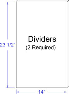
Cut two side panels 14″ wide and 41 1/2″ high from 3/4 inch oak veneered plywood. Cut two vertical divider panels 14″ wide and 23 1/2″ high from the same material.

Cut two pieces of 3/4″ oak veneered plywood 52 1/2″ wide by 14″ deep. One is for the cabinet bottom and the other for the main work shelf.

Cut the Kick Panel 52 1/2″ long by 5″ wide from 3/4″ oak plywood. Cut the notches and drill pocket holes as shown. The location of the pocket holes is not critical.

Cut the small shelf 16″ wide by 14″ deep from 3/4″ oak veneered plywood.

Cut fifteen cleats 14″ long by 2″ wide from 3/4″ oak veneered plywood. Seven of these cleats require pocket holes. All fifteen cleats require three 3/16″ diameter holes for mounting screws. The screw holes need to be countersunk. The pocket holes should be about 1 1/2″ from each end and one in the center. The screw holes 1/2″ from the pocket holes as pictured.

The reason only seven require pocket holes is that five of these cleats will be used only for drawer slide mounts for the three drawers and do not require pocket holes. This will be illustrated in the assembly instructions

Cut two cleats 19″ long by 2″ wide from 3/4″ oak veneered plywood. Drill pocket holes and mounting screw holes as for the 14″ cleats. These are for securing the workshelf and bottom to the cabinet front.

Cut two pieces of 3/4″ oak 36″ long by 2 1/2″ wide for the fluted front trim. These pieces will cover the joint and pocket holes that are used to join the three front panels together. The flutes are not necessary but if you have a router table, I think they are worth the extra trouble. Use your router with a 1/2″ core box bit to cut the flutes. The center flutes should be about 4″ from each end and the edge flutes should be about 4 3/4″ from each end. I recommend using some scrap wood to practice making the flutes. You will need to use your router table and fence for this if you have one.

Tip: make pencil marks on your router table fence on each side of the router bit, one 4″
from the center of the bit and the other 4 3/4″. Then, you can use these marks to determine the start and stop point of the work piece.

For the corner trim, you’ll need four pieces of 3/4″ oak 36″ long by 1 1/2″ wide. For the front corner trim, you’ll also need two pieces of 3/4″ oak 36″ long by 3/4″ wide. For the Top and Bottom Side trim, you’ll need four pieces of 3/4″ oak 16 1/4″ by 2″. One end of the top and bottom trim requires a 45 degree miter cut because it must mate with the front top and bottom trim.

Cut two pieces of molding 26″ long for the frame top. Cut two pieces of molding 18″ long
for the frame sides. All corners must have 45 degree miters. I made the molding from 3/4″ by 1″ wide oak and used a round over bit and ogee bit to give it the shape shown above. If you don’t want to go with the above shape, you could simply round over both sides, use a beading bit, or any other design you choose.

The top and bottom horizontal trim may need to be slightly longer if your plywood is less
than 3/4″ thick. The vertical divider trim needs to be exactly twice the thickness of the
plywood. So, if your plywood is less than 3/4″ thick, the width of these pieces will be a
little less than 1 1/2″. The pocket holes pictured on some of the pieces above are optional but you may want to use them to assemble the trim before attaching it to the cabinet.

Assembly:

  1. Attach the top horizontal trim piece 10″ from the top of the side trim pieces with pocket hole screws as shown.
  2. Attach the vertical divider trim to the top horizontal trim as shown.
  3. Attach the bottom horizontal trim to the vertical side trim and vertical divider trim as shown.
  4. Attach the drawer divider trim as shown.

Top and Armrest:

Cut List:

  • (1) 6′ Oak Arm rest Moulding
  • (2) 2′ Oak Arm rest Moulding
  • (1) 3/4″ x 63 1/2″ x 19″ Oak Plywood – Countertop
  • (1) 3/4″ x 1 1/2″ x 40 1/2″ Oak – Countertop trim
  • (2) 3/4″ x 1 1/2″ x 8″ Oak – Countertop trim
  • (2) 3/4″ x 1 1/2″ x 15 1/8″ – Countertop trim
  • (4) 5/8″ x 4 3/4″ x 2″ Pine Plywood – Countertop risers
  • (3) 5/8″ x 4 1/4″ x 2″ Pine Plywood – Countertop risers
  • (2) 5/8″ x 10 3/4″ x 2″ Pine Plywood – Countertop risers
  • (2) 5/8″  25″ x 2″ Pine Plywood – Countertop risers
  • (2) 1/2″ x 7 3/4″ x 22″ Oak Plywood – End Soffit
  • (1) 1/2″ x 54″ x 7 1/4″ Oak Plywood – Center Soffit

The illustration above shows how to cut the 45° angles with your miter saw. The 1 3/8″ by 3/4″ and the 3 5/8″ by 3/4″ spacer strips hold the molding in the same position it will be installed on the bar top. This is an easy way to make a compound miter cut.

Note: The length and width of the Bar Top depend on the exact inside dimensions of the
assembled armrest molding. I recommend you assemble the armrest molding first, then
measure the inside opening to determine the exact length and width of the Bar Top.

The cuts for the center opening must be perfectly straight and smooth so the trim can fit
flush. I recommend cutting the opening so 1/16″ to 1/8″ of material still needs to be
removed and using your router to true the edges to the exact dimensions. Attach three perfectly straight pieces of 3/4″ thick wood along the edges of the cutout to serve as router guides as shown below. Be sure to attach these strips to the bottom side so you don’t have screw holes showing on the top. Use a straight router bit with a bearing on the end and a 1″ cutting depth. Turn the workpiece over and carefully run the router along the edge guides with the bit bearing following the edge guides. After truing up the edges with your router, the inside corners will need to be carefully trimed with a file.

Countertop trim pieces are all cut from 1 1/2″ by 3/4″ solid oak.

All the risers are 5/8″ thick and 2″ wide. Since armrest dimensions may vary, the lengths given in the drawings above should be considered guidelines only. Wait until you’re ready to assemble the Bar Top before cutting the risers. Then you can tell exactly how long they need to be.

The soffit pieces are used as trim between the armrest molding and the cabinet panels. These pieces also serve to support the outer edges of the molding. The soffit is made from 1/2″ plywood. The dimensions given in the drawings above should be considered guidelines only. As with the risers, wait until you’re ready to assemble the Bar Top before cutting the soffit. Then you can tell exactly what the dimensions should be.

Drawers and Wine Racks:

Cut List:

  • (2) 1/2″ x 12 1/2″ x 3″ Oak Plywood – Top Drawer Box Front & Back
  • (2) 1/2″ x 12 1/2″ x 4″ Oak Plywood – Middle Drawer Box Front & Back
  • (2) 1/2″ x 12 1/2″ x 8″ Oak Plywood – Lower Drawer Box Front & Back
  • (2) 1/2″ x 14″ x 3″ Oak Plywood – Top Drawer Box sides
  • (2) 1/2″ x 14″ x 4″ Oak Plywood – Middle Drawer Box sides
  • (2) 1/2″ x 14″ x 8″ Oak Plywood – Lower Drawer Box sides
  • (3) 1/4″ x 13 1/2″ x 13″ Hardboard – Drawer Bottoms
  • (1) 3/4″ x 15 1/2″ x 5″ Oak – Top Drawer Front
  • (1) 3/4″ x 15 1/2″ x 6″ Oak – Middle Drawer Front
  • (1) 3/4″ x 15 1/2″ x 10″ Oak – Lower Drawer Front
  • (5) 14″ Drawer Slides
  • (2) 3/4″ x 18″ x 14″ Oak Plywood – Wine Rack Bottom
  • (2) 3/4″ x 18 3/4″ x 2 3/4″ Oak – Wine Rack front
  • (2) 3/4″ x 18″ x 1 1/4″ Oak – Wine Rack Back
  • (6) 3/4″ x 12 1/2″ x 3″ Oak – Wine Rack center Divider
  • (4) 3/4″ x 12 1/2″ x 1 1/2″ – Wine Rack Side

If your plywood is exactly 1/2″ thick, the above dimensions will produce a finished drawer width of 13 1/2″. This leaves 1/2″ on each side for the drawer slides. If your plywood is not exactly 1/2″ thick, you will need to adjust the length of fronts and backs accordingly so your finished drawer box width is 13 1/2″. The drawer box sides should still be 14″. You’ll need to cut a slot just slightly more than 1/4″ deep along the the bottom of each of the drawer box sides, fronts, and backs. This slot should be 3/8″ from the bottom and slightly wider than the thickness of the bottom material.

Drawer fronts are made from 3/4″ solid oak

Cut the Drawer Fronts from 3/4″ solid oak. You’ll probably need to glue up some narrower
pieces for the bottom drawer front. The cutout diagrams show a 6″ and 4″ section for making the lower Drawer Front. The fronts will be attached to the boxes and are wider and taller than the boxes so they will overlap the rear cabinet trim. After cutting the fronts to the correct dimensions, you’ll want to put a decorative edge along the edges with your router. I used an ogee bit on the prototype but it’s all a matter of taste. You’ll need three drawer bottoms. These are all the same size. You can use 1/4″ thick hardboard or 1/4″ thick plywood as you prefer.

Cut the wine rack bases 18″ wide by 14″ deep from 3/4″ oak veneered plywood. Drill three
pocket holes along the front edge of the top surface as shown. One in the center and one on each side about one inch from the edges. You’ll need one base for each wine rack you add to your bar. Cut the dividers from 3/4″ solid oak as shown above. You’ll need three dividers and two sides per wine rack.

Cut the wine rack fronts 18 3/4″ wide by 2 3/4″ high from 3/4″ solid oak. Cut the half circle cutouts as shown above.

If you will be adding drawers to your bar, attach the drawer slides to cleats as shown. Three must have the roller on the right and three must have the roller on the left. The lowest part of the drawer slide must be flush with the bottom of the cleat. The roller section must protrude past the end of the cleats by 3/4″ (the thickness of the trim).

Attach three cleats with drawer slides to the left side as shown above. Attach two cleats with drawer slides to left divider panel as shown above. Note: The bottom cleat and drawer slide for the left divider is attached to the bottom with pocket holes later. It will then provide a way to attach the left divider to the bottom.

If you will be including wine racks, in your bar, attach the drawer slides to the divider panels as shown. Note: the drawer slides for the wine racks do NOT protrude 3/4″ past the edge of the divider panels. This is because the wine rack fronts will be flush with the opening while the drawer fronts will be on the outside of the opening.

Attach the cleats to the top surface of the bottom plate as shown. Pocket holes sides should be placed 16″ from the ends with pocket hole sides facing each other as shown. (These cleats are used for mounting the vertical panels to the bottom surface.)  Attach two cleats to the ends of the bottom surface with pocket hole screws. These cleats are flush to the edges of the bottom.

Attach the vertical dividers to the cleats as shown. Attach the front cleat between the panels as shown with pocket hole screws.

Turn the assembly upside down and attach the kick panel as shown with pocket hole screws. Note: the pocket hole screws are on the back side of kick panel.

Now, attach the four cleats to the bottom side of the work shelf with pocket hole screws as shown. The end cleats have pocket holes facing out. The middle cleats have the pocket holes facing each other. The pocket hole side of the middle cleats are placed 16″ from the ends of the workshelf.

Assemble the three front pieces as shown and secure with pocket hole screws. These screws will be covered with trim later.

Attach the front to the cabinet assembly. Use finishing nails to attach the front to the sides (these nails will be covered with trim later.) From the back side, use 1 1/8″ screws through the two front cleats to attach the front to the bottom and the workshelf.


Install the Foot Rail Brackets as shown. Your hardware may be different, so be sure to take your own measurements. Position one bracket so the foot sets flat on the floor and measure the distance of the mounting holes from the floor. This should be about 5 1/2″. The rest of the brackets must all be the same height.

The rear edge of the side brackets should be two inches from the rear vertical trim. The front brackets should be centered side to side between the trim.

Place a piece of tubing in the front supports as shown and measure the distance “X”. (The rear of the cabinet trim to the edge of the tubing.) This should be about nineteen or twenty inches. This will be the length of the tubing for the sides.

Insert a piece of tubing in each side support as shown. Have someone help you hold them so they are parallel to the cabinet and the floor. Measure the distance “Y”. This is the length of the front tubing.

Assemble the rails as shown to the left. The end caps go into the rear of the side rail sections. I recommend completely assembling the rail with the screws provided in the kit and tighten all the screws enough so they make visible marks on the brass rail sections. Then, disassemble the rail and drill 3/16″ holes in the rail where the screw marks are so the screws will all fit flush with the bracket surfaces, elbow collar surfaces, and at the end caps. Since the end caps are inserted into the ends of the rail sections, their screw heads will be on the outside of the rail section.

These photos show a couple of ways to attach the molding corners.

You can join the corners with pocket holes as shown in Figure 1. You’ll need a small pocket hole jig for this. Note: Be sure to place the pocket holes so the screws don’t come through the top surface of the molding. Shorter screws may be necessary. Apply glue and secure with pocket hole screws. You can secure the joints with finishing nails by temporarily securing the corners using some scrap plywood with pocket hole screws as shown in Figure 2. Drill two pocket holes on each of two sides of the plywood. Glue some 100 grit sandpaper to the surface of the scrap plywood where it contacts the lip of the molding (This makes it grip tighter.) Apply glue to the molding joint then secure the molding with the scrap plywood to hold the joint firmly together. Turn the assembly over and secure with two finishing nails as shown (Be sure to pre-drill the nail holes so you don’t split the wood). Countersink the nails so you can fill with putty later. Then you can remove the scrap plywood. The soffit which will be added later will serve to re-enforce the corner joints.

The pocket holes along the back and cutout are for mounting the trim. The ones that are not marked may be placed in approximately the position shown.

Attach the top trim with glue and pocket hole screws as shown above. To ensure the top surfaces of both the Trim and Top are flush, clamp both pieces to a flat surface before inserting pocket hole screws.

This illustration shows how to clamp a piece of trim to plywood. One clamp holds the trim piece flush to a flat surface and the other clamp holds the plywood flat to the same surface. In this case, the plywood represents the bar top. To keep the pieces flush along the whole piece, you’ll want to move the clamps close to each pocket hole as you insert the screws. This will ensure the trim is flush with the top surface.

Apply some glue and arrange the risers on the underside of the top as shown. Attach with either 1 1/8″ flathead screws or 1″ finishing nails.

Note: Even though 1 1/8″ screws won’t penetrate the plywood, they may cause unsightly bumps on the top surface. To avoid this, pre-drill the screw holes in the plywood with a bit slightly larger than the inner diameter of the threaded section of the screws.

The above illustration shows now the armrest molding, countertop, risers and soffit fit together.

Attach the assembled top to the molding assembly with pocket hole screws as shown. Do not glue the top to the molding.

Attach the end soffit pieces to the molding with 1″ flat head screws. Attach the end soffit pieces to the risers with 1 1/8″ pan head screws.

Attach the center soffit pieces to the outside edge of the molding with 1″ pan head screws. Attach the center soffit pieces to the risers with 1 1/8″ pan head screws.

This should leave an opening that is 54″ between the end pieces of soffit and 14 3/4″ between the center soffit and the rear trim. This is the size of the outside dimensions of the cabinet top and this opening must fit over the cabinet top.

This drawing shows an upsidedown view of how the cabinet and top are attached. Use two corner brackets on each end and three in the middle. You don’t want to actually turn the bar upside down to attach the top, it may damage it. Spacing of the corner brackets is not critical. The cabinet trim is not shown for clarity.

Note: You should predrill the bracket screw holes in the top and use screws that go no more that 1/2″ into the wood. Otherwise, the bracket screws may cause unsightly bumps on the top surface of the Bar Top.

Apply a little glue to the mating surfaces and assemble the drawer boxes.

Assemble the front, back, and right side with 1″ long finishing nails as shown in Step 1. Insert the bottom as shown in Step 2. Attach the left side as shown in Step 3.

Support the drawer boxes with 1/2″ thick strips of wood and attach the drawer fronts with 1 1/8″ screws as shown in Step 4. This is necessary because the bottom of the front must be 1/2″ below the bottom of the box so it will overlap the rear cabinet trim when installed. Next, attach the drawer slides as shown in Step 5.

Apply a little glue to the mating surfaces and assemble the wine racks as shown.

Mount the front to the base with pocket hole screws. The base and front are flush on the bottom and the base is centered between the edges of the front.

Two edge dividers are mounted flush with sides of the base. The center one is centered and the other two are 4 1/2″ from the edge of the base to the center of the dividers.
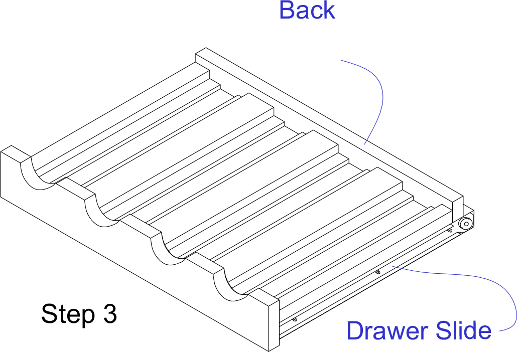
Attach the back to the base with finishing nails or screws as you prefer. Attach the drawer slides as shown with the screws that were provided with the drawer slides.

This completes the assembly of your home bar. Be sure to countersink and fill all finishing nails holes before applying the finish.

Cut Out Suggestions:

These layout diagrams show how to cut the parts from two pieces of 3/4″ oak plywood. Note: Since the Center Front Panel and Small Shelf are almost square, they have an indicator arrow and dimension line to ensure you have the grain oriented properly. The other parts are more obvious since they are not as close to being square. You can cut the small shelf a little larger than it’s listed size with a jig saw and true it up with a table saw since it will still have one straight edge.

Cutout diagrams for the soffit and drawer box parts from 1/2″ oak plywood. Cutout diagrams for risers are not given as they may be made from scrap wood.

The drawer bottoms are made from 1/4″ hardboard.

The original plan can be found at http://www.bobsplans.com

 
[email_link]
Bar Table

I know a lot of you are like me in that you build to get exactly what you want while save money, and I love the cost factor of these plans.  If you already have a scrap piece of 3/4″ plywood, the materials to build the rest of this table are about $10.  Seriously.  If you have to buy a 2’x4′ sheet of plywood, the whole table will cost about $25.  So, lets say you want to build the table and 4 bar stools for your family and have nothing to start with.  That’s a whole dining set for $65!  That’s half the cost of ONE bar stool if you bought the original from West Elm!

Materials:

Wood:

  • 1 – 1×3 @ 4 feet long
  • 3 – 2×2 @ 8 feet long
  • 1 – 2×4 @ 8 feet long
  • 1 – 1/4 sheet of 3/4″ plywood


Hardware and Supplies:

  • 1 1/4″ Pocket Hole Screws
  • 2 1/2″ Pocket Hole Screws
  • Wood Glue
  • Wood Filler
  • Medium Grit Sandpaper
  • Primer or Wood Conditioner
  • Paint or Stain

Cut List:

Boards:

  • 2 – 1×3 @ 21″ – Side Aprons
  • 1 – 2×2 @ 45″ – Center Base
  • 4 – 2×2 @ 21″ – Top/Bottom Sides
  • 4 – 2×2 @ 42″ – Table Legs
  • 2 – 2×4 @ 45″ – Center Aprons

Plywood:

  • 1 – 3/4″ Plywood @ 45″ x 21″ – Table Top

Make sure to re-measure and check for square after every step.  Sometimes when building your measurements can be off very slightly, and it’s important that your numbers are exact.  (Especially when working with doors and drawers!)  Measure your available space before building this plan to make sure that it will fit.  Please read through the entire plan before getting started.

Step 1:

Attach your top/bottom and table legs together using your Kreg Jig.  Remember to place your pocket holes for the bottom piece strategically facing the bottom of the frame and toward the interior of the table on your top piece so you have no holes to fill later.

Step 2:

Set aside your table legs for a moment to build the table top.  (Pictured above is a bottom view of your table top.)  Make sure to pre-drill all of your pocket holes as shown above in your table top before attaching anything.  This will help you in later steps.  When attaching your 2×4 center aprons to your plywood top, make sure each of the edges are flush.

Step 3:

Attach the legs you built in step 1 to the table top you built in step 2 using the pocket holes that you predrilled and some wood glue!

Step 4:

Attach 1×3 side aprons into the 2×4 from your table top using your Kreg Jig.  Remember to drill those pocket holes from the inside to hide them!  The bottom of your 1×3 will not be exactly even with the bottom of your 2×4.  Don’t worry, it’s part of the design!

Step 5:

Attach your 2×2 center base in between your two table legs using pocket holes drilled from the underside. It should sit centered on each side, leaving a 9 3/4″ gap on the bottom side 2x2s (not including the legs).

Finishing:

Finish your project as desired.  Make sure to sand it down with medium grit sand paper and fill in all your holes with wood filler before tackling that paint or stain.


The original plan can be found at http://www.oldpaintdesign.com

 
[email_link]
 

1 2