BBQ & Grill Carts

Gridview


BBQ Grill and Cooler Table

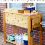
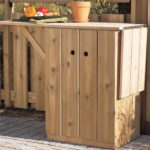
Today I’m going to show you How to Build a Patio Cooler and Grill Cart Combo.  The grilling season is upon us!  The cool weather is making an exit and the heat, BBQ, and outdoor parties are here.  Two things I’ve been thinking of building are a patio cooler and a grill cart.  Since my back deck is not huge I decided to kill two birds with one stone and show you guys how to make a DIY patio cooler box and BBQ cart in one.

The project is made from cedar to withstand the elements and give it a nice classy look.  The heart of the cooler box side is 48 qt cooler with plenty of capacity for your parties.  The grilling side has a storage compartment and hooks to hold all your BBQ accessories.  The lid for the storage box is flush with no hinges or handles giving you a 22″ x 20″ landing space for food and other barbecue fixings.  The assembly is easy and straight forward so read ahead and get ready to get your summer outdoor entertaining game on point!

Materials:

  • (13) 12′ 1×4 cedar boards
  • 1-1/4″ Pocket Hole Screws
  • 1-1/4″ Exterior Screws
  • 48qt Cooler
  • 3″ utility hinges
  • Front handle
  • Bottle Opener
  • Single Hooks
  • Hose Bib
  • (2) 1/2″ Male PVC Adapter
  • 1/2″ PVC Pipe
  • 1/2″ PVC Nut

I built the cooler box and grilling station entirely out of 1×4 cedar.  My local lumber supplier had 12′ boards that were rough on one side and I was able to get them for half the price of what you would pay at the big box store for the cedar 1x4s.  If this is an option for you then you can save some significant money going this route.

Building the Patio Cooler Base

You’ll start by building the top frame based on the size of your cooler.  The top of my cooler was 23-3/4″ x 13-1/2″.  If your cooler is a different size then you’ll need to adjust the top frame accordingly and see if you need to adjust the base as well.

Cut 2 boards to 50″ for the long top frame pieces and 3 boards to 13-1/2″ for the short top frame pieces.  Drill pocket holes in the ends of the short pieces and assembly with 1-1/4″ pocket screws.  This will give a 15-3/4″ opening for the grilling storage box.

Cut 8 boards down to 38-1/4″ long for the legs.  Rip down 4 of these boards to narrow leg pieces at 2-3/4″ wide.  Use a pocket hole jig to drill pocket holes in the 2-3/4″ pieces in the top 13″ of the leg and another hole 2″ up from the bottom.

Join the narrow leg pieces to the wide pieces glue and 1-1/4″ pocket hole screws on the top and bottom.  In the gap where there are no pocket holes, use clamps to hold the joints tight.  Make two legs with the narrow pieces on the right side and two with the narrow pieces on the left side.  This lets you have the wide face of the legs showing on the front and back of the cooler.

Cut 8 pieces of side cladding to 16-1/2″ long.  Use a trim router to route a 1/16″ 45 degree chamfer on the outer edges of each board.  This will give the boards a nice beadboard look when butted together.

Lay two legs down and starting from the top, attach 4 side cladding pieces to the legs with two 1-1/4″ screws on each side of each board. Repeat this process with the other 2 legs to form 2 side assemblies.

Cut 4 pieces of front cladding and 4 pieces of back cladding to 44-1/2″ long, and route a chamfer on the long edges just like the side cladding.  Side the side assemblies on edge and starting at the top, attach the front cladding to the sides with 1-1/4″ screws.

Flip the assembly over and now attach the 4 back cladding pieces to the sides.  Now you have the base of your patio cooler and grill cart combo!

Cut two 3/4″ x 3/4″ top front cleats 14″ long and one top side cleat 11″ long.  Predrill holes on the bottom for attaching the top frame later.  Secure the 11″ cleat to the middle of the right side flush with the top and secure the 14″ cleats to the front and the back 1-1/2″ away from the right side.

Make the Grill Cart Storage Bay and Bottom Shelf

Attach two 1″ wide 14″ long cleats to the inside of the front and back walls, 18″ from the right side.  Cut four 15″ wide storage divider boards and glue and screw them to the cleats to create the storage bay.


Cut and install two 17-1/4″ cleats to the front and back of the storage bay.  Put them 3/4″ up from the bottom of the bay then attach five 15″ storage bay bottom pieces to the cleats with screws from underneath.  The middle board will need to be trimmed to fit.


Attach the top frame to the base with pocket hole screws on the cooler side and with 1-1/4″ screws through the cleats in the storage bay.  Use glue on all the top surfaces for a good hold.

Cut two 46″ long 1″ wide shelf stretchers and eleven 16-1/2″ shelf slats.  Attach the slats to the stretchers with glue and a brad nailer.  For consistent spacing start with the outer slats and then secure the middle slat.  From there fill in the gaps spacing the slats 3/4″ apart.

Test fit your cooler in the opening and remove the cooler drain plug.  Reach a marker through the cooler drain and mark a spot on the left side of the patio cooler.  Drill a 1-1/4″ hole in the side for the plumbing fittings.

Flip the grill cart combo over and put the cooler in place.  Secure the cooler by installing three 15″ cooler supports into the front and back with 1-1/4″ pocket screws.

Making the Cooler Box and Grill Bay Lids

Flip the cooler back over and cut four 15-3/4″ long storage bay lid pieces.  Put a chamfer on the boards with the trim router like the body cladding.  Drill a 1″ hole in the middle of one board and chamfer the top edge of the hole.

Cut two 13-1/2″ by 1″ wide lid battens.  Line the lid boards up together with the board with the hole at one end and fasten the boards together using the battens, glue and 1-1/4″ screws.

Make 4 small 1-1/2″ x 2″ storage lid tabs.  Round one corner of the tabs and install them in the top corners of the storage bay with glue and brad nails into the top corners of the storage bay.

Build the frame around the lid by based on your own cooler measurements.  The sides should be 3/4″ taller than your lid.  I cut two lid front/back pieces to 25-1/4″ by 2″ and two side piece 13-1/2″ by 2″.  Join the lid frame with 1-1/4″ pocket hole screws.


Cut 3 lid support cleats to 13-1/2″ by 1″ and attach them to the front and back with pocket holes. Place the outer cleats so they are directly over the side ridges on your lid that mate with the cooler body. You’ll be screwing into the lid later and don’t want the screws to pop through the underside of the lid.

Make 5 lid top pieces out of 25-1/4″ boards.  Route the 45 degree chamfers on these boards just as the others.  Layout the boards on the top and cut the center piece to width to fit.  Use super glue and temporarily affix the full size boards to the edges of the frame.

Flip the lid over and permanently attach the lid boards to the cleats with 1-1/4″ screws.

Flip the lid over again on top of the cooler.  Now secure the top to the cooler lid with 1-1/4″ screws through the outer cleats into the lid.  Attach the center board with wood glue on the center cleats and super glue on the outer edges.  The super glue will bond quickly and the wood glue will give a long lasting hold.  Assembling the lid this way give you a super clean look with no nail or screw holes…SCORE!

Installing the Cooler Drain & Lower Shelf

Remove the drain from your cooler and keep the washer on the inside.  Get two 1/2″ PVC male threaded adapters, a length of 1/2″ PVC, a 1/2″ nut and a hose bib for the outside of the cooler.

The length of the PVC pipe will vary per installation.  Cut a hose bib mounting block to 3-1/2″ by 3-1/2″ and drill a 1″ hole through it for the male adapter.  You may need to drill a larger hole with the collar if the fitting won’t go through.  Glue up the final PVC parts and install them on the hose bib and mounting block.  Put wood glue around the mounting block and insert the assembly into the cooler and lock in place using the nut in the cooler.

Sand everything down to 150 grit and apply your finish at this point.  I used a Spar Urethane made for outdoors.

After the finish is dry, install the lower shelf so the bottom is 2-1/2″ up from the floor.  I would recommend turning the patio cooler on it’s top to do this vs. laying it on its back like I did

Hardware for the Patio Cool / Grill Cart Combo

The cooler lid gets 3″ utility hinges and a handle on the front.

I added a bottle opener on the front and 2 hooks on the grilling side of the cart as well.

I put my inserts for my STOK Quattro grill into the storage side and it worked great to hold them all.  I just put some little dividers in there to keep them separated.

Alright, you’re all finished up!  Put the patio cooler and grill cart combo out on your deck and let the good times roll this summer.

The original plan can be found at http://fixthisbuildthat.com

 
[email_link]
 

Backyard Service Cart

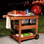
A practical service cart with fold-able shelves that is indispensable next to a barbecue.
This service cart is built with cedar, a naturally weather resistant wood that will last
for many years.

Materials:

  • 10 pieces – 1×6 Cedar – 96″ long
  • 3 pieces – 1×2 Cedar – 96″ long
  • 1 1/2″ screws for treated wood
  • 3 – 36″ piano hinges

Cutting Plan:


1×6 Cedar:

  • A – Contour – 10 pieces – 6″ x 32″
  • B – Door – 4 pieces – 6″ x 28 3/4″
  • C – Top – 3 pieces – 6″ x 23 7/8″
  • D – Shelf – 6 pieces – 6″ x 17″
  • E – Shelf – 3 pieces – 6″ x 20 7/8″
  • F – Base – 2 pieces – 3″ x 20 7/8″
  • G – Base – 2 pieces – 3″ x 15 1/4″

1×2 Cedar:

  • H – Stiffener – 10 pieces – 2″ x 15 1/4″
  • I – Stiffener – 2 pieces – 2″ x 20 7/8″
  • J – Stiffener – 4 pieces – 2″ x 9 3/8″
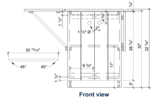
  • K – 45 degree support – 2 pieces – 2″ x 20 15/16″

Piano Hinge:

  • L – Door hinge – 2 pieces – 28″ long
  • M – Shelf hinge – 1 piece – 15″ long

Assembly:

Step 1:

Assemble each of the two sides by juxtaposing three A boards, connected by three H stiffeners and a G stiffener, centered in relation to the three boards.

– Screw an H stiffener to the higher end of the A boards.
          – Screw the G stiffener to the lower end. Note that this G part is made of a 1″ x 6″ part cut length ways 1″ x 3″.
          – Attach the last two H stiffeners on both sides at the centre of the assembly, 15 1/2″ from the lower end of the A boards.


Step 2:

Assemble the back by juxtaposing four A boards, connected by an I stiffener and an F stiffener centered in relation to the four boards.
– Screw the I stiffener to the higher end of the A boards.
– Screw the F stiffener to the lower end.


Step 3:

Attach the back of the sideboard
to the sides. The back should rest on the sides, and not be caught between them.

Step 4:

Screw an I stiffener on the front
to the two H stiffener above
the side panels.

Step 5:

Screw an F stiffener on the front to two G stiffener of the side panels.


Step 6:

Lay the E boards of the interior shelf on the central H stiffeners, and screw.

Step 7:

Lay the C boards on the higher H stiffeners. The C boards should be centered in relation to the sides. Screw.


Step 8:

Assemble the two hinged shelves by using three D parts, connected
by H stiffeners attached 2″ from the ends of the D boards.

Step 9:

Screw the piano hinges M to the shelves, and then to the sideboard.

Step 10:

Assemble each door by using two B parts connected by J stiffener
that are centered and placed 1 1/2″ from the ends of B.

Step 11:

Assemble each door by using two B parts connected by J stiffener
that are centered and placed 1 1/2″ from the ends of B.

Step 12:

Screw the L piano hinges to the doors and then to the sides of the sideboard.

Step 13:

Support of the hinged shelves, when unfolded, is ensured by the K parts,
which ends are cut at 45 degrees, and are supported by the central external stiffeners.

Although the cedar is weather resistant, it is recommended to store the sideboard during the winter to give it a longer life.


The original plan can be found at https://www.rona.camade by Rona

[email_link]

Barbeque Cart

This easy-to-build Barbecue Cart will solve both of those problems for you.  First, it comes complete with two spacious drawers, a condiment organizer, a utensil holder, a slide-out cutting board/shelf and plenty of space for all the cooking stuff you’ll be needing.  The laminate-covered top offers plenty of space for food preparation and staging . . . it’s conveniently portable . . . plus . . . it’s attractive enough to fit in, no matter where you may choose to store it between cook-outs.

We made our example from red oak with a white laminate-covered top and lower shelf.  If you’re planning to leave the table outside, be sure to choose a weatherproof wood like red cedar, redwood or cypress for the basic construction and use waterproof glue and brass screws to put everything together.

List of Materials:

Facing Assembly – Figure 1
A – Stiles(2) 3/4″ x 1 1/2″ x 8″
B – Stile-Middle(1) 3/4″ x 1 1/2″ x 4 1/4″
C – Top Rail(1) 3/4″ x 2 1/4″ x 17″
D – Bottom Rail(1) 3/4″ x 1 1/2″ x 17″

Base Assembly – Figure 2
E – Back(1) 3/4″ x 8″ x 20″
F – Sides(2) 3/4″ x 8″ x 14 1/2″
G – Legs(4) 2″ x 2″ x 38″

Web Frame Assembly – Figures 3 & 4
H – Stiles(2) 3/4″ x 2 1/2″ x 17″
I – Rails(2) 3/4″ x 2 1/2″ x 15 3/4″
J – Stile-Middle(1) 3/4″ x 2 1/2″ x 12 3/4″
K – Drawer Runners(2) 1/4″ x 1″ x 16″
L – Cleats(2) 3/4″ x 2 1/2″ x 16 7/8″

Shelf Support Assembly – Figures 6 & 7
M – Sides(2) 3/4″ x 1 5/8″ x 22 1/4″
N – Back Brace(1) 3/4″ x 1 5/8″ x 12 3/4″
O – Front Brace(1) 3/4″ x 3/4″ x 12 3/4″
P – Guides(2) 3/4″ x 1 1/4″ x 10 3/4″
Q – Side-Out Shelf(1) 11/16″ x 10 3/8″ x 11 1/16″
R – Bottom-Hardboard(1) 1/8″ x 14 1/2″ x 11

Bottom Shelf Assembly – Figures 8 & 9
S – Front/Back Rail(2) 3/4″ x 1 1/2″ x 20
T – Side Rail(2) 3/4″ x 1 1/2″ x 18 1/2″
U – Top-Laminate(1) 3/4″ x 17″ x 18 1/2″

Drawer Assembly – Figure 5
V – Sides(4) 5/8″ x 4 1/16″ x 16″
W – Front/Back(4) 5/8″ x 4 1/16″ x 6 7/8″
X – Bottoms(2) 1/4″ x 6 3/4″ x 15 1/8″
Y – False Fronts(2) 3/8″ x 5″ x 8 1/2″

Top Assembly
Z – Top-Laminate(1) – 3/4″ x 17″ x 18 1/2″
M – Side Rail(2) – 3/4″ x 1 1/2″ x 20 1/4″
BB – Front/Back Rail(2) – 3/4″ x 1 1/2″ x 25 3/4″

Accessory Add-ons
CC – Utensil Holder(1) 3/4″ x 2″ x 17 5/8″
DD – Condiment Hold(1) 3/4″ x 4″ x 18″

Hardware
20 – 1 1/4″ x #8 Wood Screws
14 – 1 ¼” x #6 Wood Screws
4 – Wooden Screw Plugs – Optional
62 – 1” x 3/8” Dowel Pins
1 – 1” x ¼” Dowel Pin
2 – Drawer Pulls
1 – Sliding Shelf Pull
4 – Casters

Figure 1

Step 1:

First, cut all work pieces to size, following the dimensions outlined in the List of Materials

NOTE:  Be sure to allow all glued-up sub-assemblies to dry completely for 24 hours before putting them together with other sub-assemblies.

Step 2:

Using your drill press, drill (16) 3/8-inch diameter by 9/16-inch deep dowel holes in pieces B, C and D, and glue the facing assembly together, using 3/8-inch diameter by 1-inch long dowel pins as shown in Figure 1.

Step 3:

Use your dado set-up or band-saw to cut a 10-7/16-inch wide by 1-9/16-inch deep notch in the left side of the base assembly (F) to accommodate the pull-out shelf/cutting board, which will be installed later. See Figure 2.

Figure 2

Step 4:

Drill (50) 3/8-inch diameter by 9/16-inch deep dowel holes in pieces A, E, F and G as shown in Figure 2.  Assemble all pieces together (including the facing sub-assembly you made in step #2, above) using 3/8-inch diameter by 1-inch long dowel pins.

Step 5:

Mount cleats (L) to the insides of the four legs (G) as shown in Figure 4, using 3/8-inch diameter x 1-inch long dowel pins.  Position them 7-1/4” down from the tops of the legs (G) or sides (F).

Step 6: 

Cut 1/4-inch by 3/8-inch deep tongue & groove joints in the web frame stiles and rails (pieces H, I and J), as shown in Figure 3.

Figure 3

Step 7:

Glue-up the web frame assembly as shown in Figure 3

Step 8:

Mount the web frame assembly to the top surfaces of the cleats you glued into position in step#5, above, using four 1 ¼” x #8 wood screws. See Figures 3 & 4.
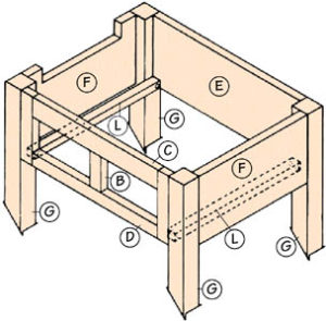
Figure 4

Step 9: 

Cut the dado and rabbet joints in the drawer fronts and backs (parts W) and the drawer sides (parts V), as shown in Figure 5.

Step 10: 

Cut the 1-inch wide by 1/4-inch deep notches in the drawer fronts/backs (parts W) (see Figure 5).  These notches will slide on the drawer runners (parts K, Figure 3) when assembled.

Step 11: 

Using glue, assemble the drawer sides (V) front/back (W) and bottom (X), as shown in Figure 5.

Figure 5

Step 12: 

Using the drawer assemblies you made in step 11, above as guides, glue the drawer runners (K) to the web frame assembly as shown in Figure 3.  Be sure the drawers slide smoothly in and out before leaving the runners to dry.

Step 13:

Using a router or belt sander, round-over the edges of the false drawer fronts (Y).

Step 14:

Glue the false drawer fronts (Y) to the fronts of the drawer assemblies (See Figure 5).

Step 15: 

Construct the shelf support assembly (M, N, O, P, R in Figure 6) using 1-1/4″ x #6 wood screws.

TIP:  Drill pilot holes for screws first to ease the assembly process. 

Figure 6

Step 16: 

Mount the completed shelf support assembly (Figure 6) to the base assembly (Figure 2), using 1-1/4-inch x #8 wood screws. See Figures 6 & 7.

Step 17: 

Drill a 1/4-inch diameter by 1/2-inch deep hole, in a centered position, approximately 1/2-inch in from the back edge of the slide-out cutting board/shelf (part Q).  Be sure this hole is in the TOP surface of the board.  This protruding dowel will serve as a stop to keep shelf from pulling out completely.  We’ll glue this stop into position later.

Figure 7

Step 18: 

Cut the miters for the bottom shelf front, back and side rails (parts S & T).  See Figure 8.

Step 19: 

Assemble the bottom shelf with 3/8-inch diameter x 1-inch long dowel pins and glue.  NOTE: Be sure to apply a liberal coat of glue around all edges of the top (U) to prevent any moisture or spills from seeping into the laminate substrate. If you’re planning to leave your Cart outdoors, use waterproof glue. See Figure 8.

Figure 8

Step 20: 

Attach the bottom shelf assembly you made in step 19 to the four legs (G) using 1-1/4-inch x #8 wood screws. We suggest that the shelf be positioned about 10-inch or so up from the bottoms of the legs.  It’s your choice. See Figure 9.

Figure 9

Step 21: 

Cut the miters for the front, back and side rails (AA & BB) of the Cart to assembly (See Figure 10). Next, cut out the utensil holder (CC) and condiment holder (DD) pieces. See Figure 10.

Step 22: 

Using glue and 3/8-inch diameter x 1-inch dowels, put the top assembly together (Z, AA, BB). NOTE:  Be sure to apply a liberal coat of glue around all edges of the top (Z) to prevent any moisture or spills from seeping into the laminate substrate. If you’re planning to leave your Cart outdoors, use waterproof glue. See Figure 10.

Figure 10

Step 23: 

Mount the top assembly to the base assembly, using 1-1/4-inch x #8 wood screws. See Figure 11.

Step 24: 

Mount the utensil holder (CC) to the side of the top assembly using two 1-1/4-inch x #8 wood screws. See Figure 10.

Step 25: 

Round the edges of the condiment holder using a belt sander or router and mount it to the laminate top with four 1-1/4-inch x #6 wood screws. See Figure 10.  If you prefer, counter-bore the screw holes and fill them with wooden plugs.

Step 26: 

Finish sand the entire Cart. Be careful not to scuff your laminate surfaces in the process.

Step 27: 

Apply a stain, oil or other finish of your choice.

Step 28: 

Install the slide-out cutting board/shelf (Q) and glue the 1/4-inch dowel pin into position as a stop.

Step 29: 

Mount the pulls of your choice on the drawers and slide-out shelf.

Step 30: 

Mount the casters

Figure 11


The original plan can be found at http://www.shopsmithhandson.com

<a href=”https://w00dworking.com/wp-content/uploads/2018/01/BBQ-cart.pdf” target=”_blank” rel=”noopener”><img class=”alignnone wp-image-2426 size-full” src=”https://w00dworking.com/wp-content/uploads/2018/01/PDF-icon-small-231×300-e1515477493230.png” alt=”” width=”50″ height=”65″ hspace=”20px” /></a>[email_link]
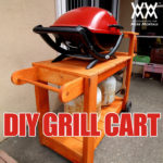
Barbeque Grill Cart

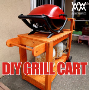
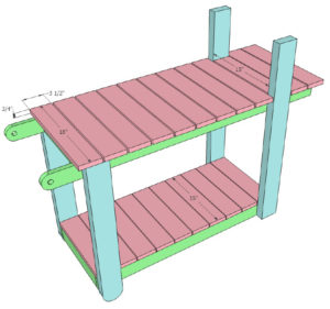
We recently bought a new gas grill to replace our old cheapie one that rusted out.  It’s a small model that requires a tabletop or a stand. Unfortunately the Weber barbecue grill cart sold separately for this grill is $100. I knew I could make something nicer for half that price.

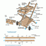
This barbecue grill cart is beg enough to hold two propane tanks on the lower shelf. I like to have two tanks in case one runs out in the middle of cooking a meal. I’ve included an elevated platform for utensils and plates and the whole unit is mobile, using the wheels from the old grill.

Materials:

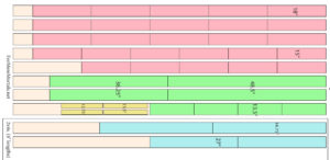
8 – 1x4x8 Cedar Boards

  • 15 pieces @ 18″ long
  • 11 pieces @ 15″ long
  • 2 pieces @ 48 1/2″ long
  • 2 pieces @ 36 1/4″ long
  • 4 pieces @ 13 1/2″ long
  • 2 pieces @ 1 1/2″ x 13 1/2″ long
  • 2 pieces @ 1 1/2″ x 12 3/4″ long

2 – 2x4x8 Cedar Boards

  • 2 pieces @ 34 3/4″ long
  • 2 pieces @ 27″ long

1 – 36″ length of 1 1/2″ dowel
2 – Wheels or castors from a old BBQ cart

Directions:

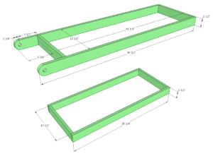
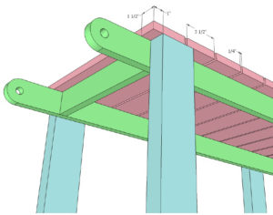
After cutting most of the pieces to length, I drilled 1 1/2″ holes in one end of each of the upper table frame. These will hold the dowel handle. I clamped the two boards together and cut both holes at once to ensure they would line up properly.

I cut a curve on the end of each of these using my bandsaw. I assembled the top frame and the lower frame into simple boxes using pocket screws.

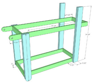
I curved the ends of the two feet. These, and the rear uprights are made from 2x4s. They get glued and screwed into the table frames. I used the wheels from the old cart and attached them using a threaded rod.


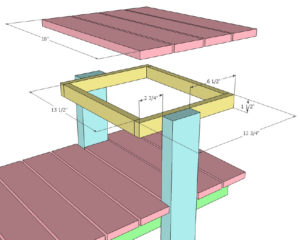
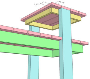
I glued the dowel handle in place and attached a frame to the upright for the utensil platform.

To protect everything, I covered all the surfaces with a transparent redwood deck stain and sealer, then screwed all the plans into place on the frames.

The original plan is found at Woodworking for Mere Mortals at https://woodworking.formeremortals.net

[email_link]